However, problems have arisen concerning these AC and DC boat systems.
In many cases the AC system on the boat is not properly wired, or has AC leakage to the boat ground.
These problems cause leakage or fault AC currents, which can be life threatening to boat and marina personnel, and cause serious harm or failure to
underwater parts and
electrical devices on the boat.
Leakage currents through this path result in accelerated
corrosion.
AC
voltage on the AC safety ground represents a serious
electrolysis and safety problem for all boats, marina apparatus and personnel.
First, this interconnect causes all
underwater protective active elements (typically
zinc's) and the more noble
underwater metallic parts of all the boats with a DC ground connected to the AC safety ground wiring in the entire harbor to be hooked together electrically. The result is a very large area
electrolytic corrosion network, making the entire harbor into a much larger wide-spread area battery which may rapidly deplete the more active elements. This is caused by the combined effect of
galvanic corrosion from all boats.
A second form of damage is
electrolytic corrosion caused by introducing harbor AC electrical power commonly connected into the DC ground systems of boats.
This arises due to improper wiring, leakage, and AC return line
voltage drop that is inducing low levels of AC voltage into the common AC
shore power safety ground.
This can result in depletion of both the active elements, and the more noble underwater elements of a boat.
This type of damage is particularly insidious, because it attacks all through
hull fittings, corroding and eventually destroying them, so the boat can easily be subjected to flooding due to failure of the through
hull fittings.
This phenomenon has reportedly caused unprotected or unmanned boats to sink at the dock.
Even wet, normally non-conductive underwater material, like wooden hulls, have been reported to be damaged by this action.
It is also a common problem in destroying conductive surfaces including
copper based bottom paint.
The unbalanced current can be leaking off through the water into the marina, or through the AC safety ground.
This type of fault has reportedly killed persons by
electrocution that were swimming, were in or on, or went into the water near a boat with this type of failure.
This type of failure in an otherwise properly wired boat may be caused by movement of
electrical contacts touching each other in an electrical distribution panel, or by sea water invading a circuit that is intended to be insulated, but leaks off to ground through the wet area.
Some electrical systems, like refrigerators, heaters, air-conditioners, or
timer run devices may have faults that do not activate until switched on unexpectedly, long after the operators have departed the boat.
A fourth common damage prevention deficiency is the ability to test, isolate both AC and DC faults and leakage, and document deterioration trends.
However in this system there is no protection for the boat or personnel from AC currents, which may be faulty from the marina power source.
However this system does not provide protection against faulty AC marina supply systems.
However this patent provides no protection against faulty AC marina supply sources.
The reference points out that any voltage above about 2.5 volts RMS could conceivably be dangerous when contacted by a person in the water.
However this reference does not provide
corrosion protection below the stated level, or against the AC marina supply system that is faulty for reasons other than externally induced stated levels of the boat to dock ground connection.
Further, this is a relatively complicated system with many circuits, parts, and expensive electrical components, resulting in decreased reliability and increased cost.
Commercial vessels are primarily concerned with minimizing self induced
corrosion over dispersed, not easily replaced galvanic elements on the vessel itself, primarily at sea, while a
primary problem on small recreational boats is prevention of external corrosion effects while in port.
Further, It claims to only provide an indicator, or alarm for external stray currents (although not identified in detailed
mechanization) and does not protect against those stray currents.
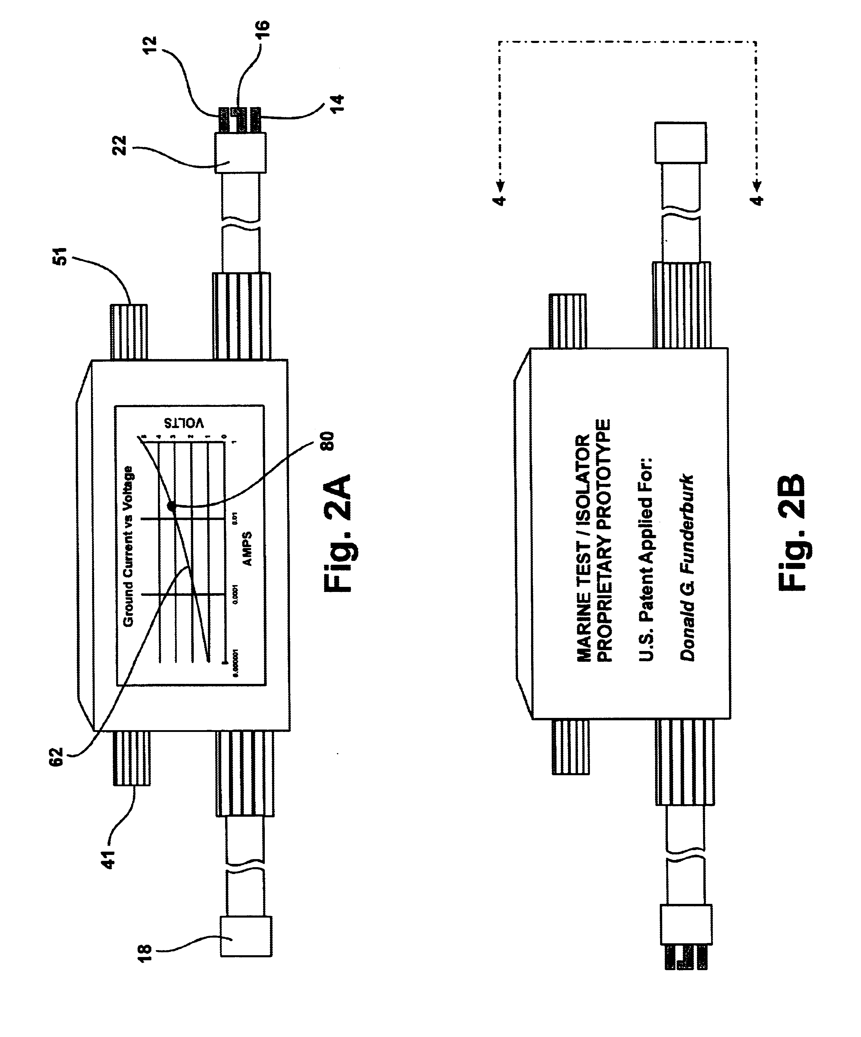
Typical Marina AC ground voltage problem levels may be well in excess of 3 volts peak.
This is primarily due to the increasing number offending recreational boats plugged in at marinas.
It is specifically noted that the device is a complex electromechanical
mechanization with many components, therefore being subject to relatively poor Mean Time Between Failure (MTBF) performance due to large parts count and failure prone
moving parts.
Unlike that device, the T / I device herein proposed does not include a
capacitor, nor propose to allow either AC or DC ground faults to continue unabated, since either can be very destructive.
This suffers from the AC limitations identified in other patent reviews above.
The reference does not disclose protecting the boat and personnel against faulty marina AC supply sources.
Heat is a major contributor to typical failure mechanisms of any device, particularly
solid state devices, thus potentially rendering any device, independent of it's intent or merit, to fail to accomplish it's intended purpose.
Furthermore, it is a very complicated system with many circuits, parts, and expensive electrical components, resulting in decreased reliability and increased cost.

