Optical diffusing plate, optical element and liquid crystal display
a technology of optical elements and optical diffusing plates, applied in the direction of optical elements, polarising elements, instruments, etc., can solve the problems of chromic emission of light, inability to apply to a reflected type liquid crystal display, and difficulty in manufacturing
- Summary
- Abstract
- Description
- Claims
- Application Information
AI Technical Summary
Benefits of technology
Problems solved by technology
Method used
Image
Examples
example 1
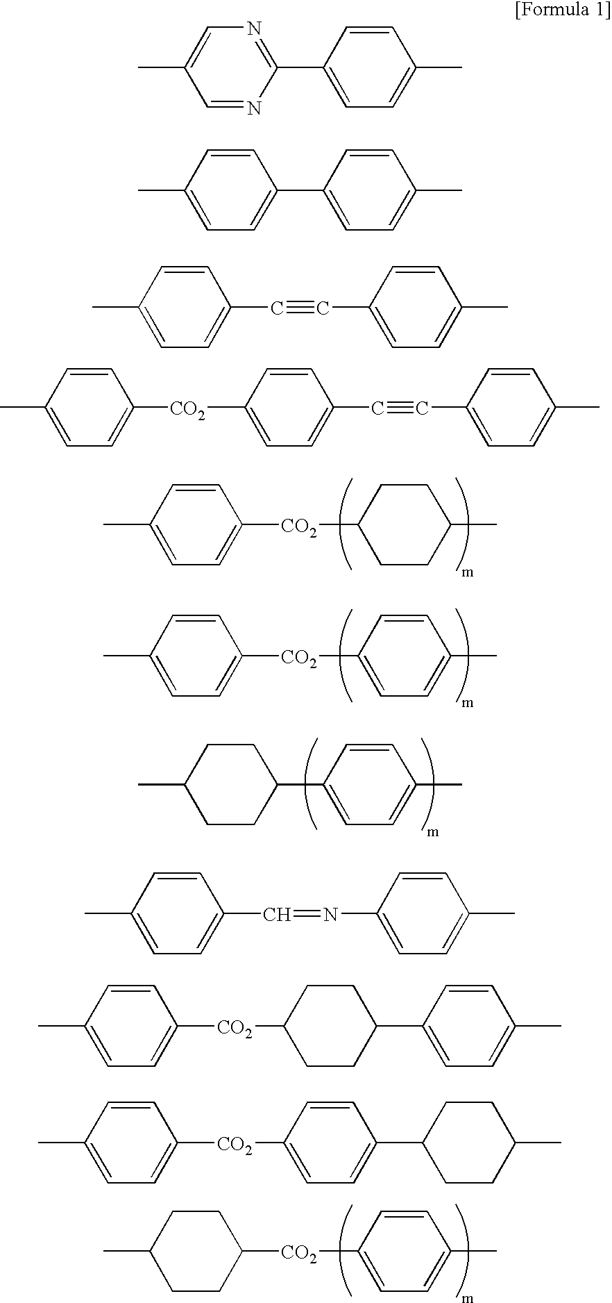
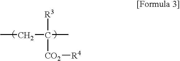
A 25 weight % toluene solution containing 100 parts of norbornene series resin (brand name Zeonex, by Nihon Zeon Corporation) comprising hydrocarbon as base material polymer of a birefringent stretched film and 6 parts of a side chain type liquid crystal polymer represented by the formula [Formula 5] shown below (where n=35, in molar % of monomer unit, shown in block for convenience, weight average molecular weight: 10000) were mixed together. A film with a thickness of 100 .mu.m was obtained from the mixed solution by casting method. The film obtained was stretched at a stretching ratio of three at 160.degree. C. to obtain an optical diffusing plate comprising a birefringent stretched film that contains the minute domain of the above-mentioned side chain type liquid crystal polymer in a dispersed state. ##STR5##
In the above-mentioned birefringent stretched film, a norbornene series resin forms a film, in which a side chain type liquid crystal polymer is dispersed having a shape of ...
example 2
An optical diffusing plate obtained in Example 1 and a commercially available polarizing plate that has 41% of total light transmittance, and 99% of polarizing degree of a transmitted light were adhered through an acrylics series adhesive layer so that the direction of a stretching axis and the transmission axis might correspond, and an optical element was manufactured.
example 3
A polarizing plate, a TN liquid crystal cell, and the optical element obtained in Example 3 were adhered one by one through an acrylic series adhesive layer on a diffuse reflection plate so that the polarizing plate might be configured at the cell side, and a reflected type liquid crystal display illustrated in FIG. 4 was obtained. In addition, the polarizing plate was configured so that the direction of a transmission axis might correspond with each rubbing direction that meets a liquid crystal cell.
As a result of investigating brightness in a displaying state with a brightness meter for the liquid crystal display obtained in Example 3, a significant improvement in brightness was confirmed compared with the case where only a polarizing plate was used.
PUM
| Property | Measurement | Unit |
|---|---|---|
| length | aaaaa | aaaaa |
| length | aaaaa | aaaaa |
| thickness | aaaaa | aaaaa |
Abstract
Description
Claims
Application Information
 - R&D
- Intellectual Property
- Life Sciences
- Materials
- Tech Scout
- Unparalleled Data Quality
- Higher Quality Content
- 60% Fewer Hallucinations
Browse by: Latest US Patents, China's latest patents, Technical Efficacy Thesaurus, Application Domain, Technology Topic, Popular Technical Reports.
© 2025 PatSnap. All rights reserved.Legal|Privacy policy|Modern Slavery Act Transparency Statement|Sitemap|About US| Contact US: help@patsnap.com


