PPL arrangement, charge pump, method and mobile transceiver

a technology of ppl and charge pump, which is applied in the direction of electrical apparatus, pulse automatic control, etc., can solve the problems of non-linearity around the "lock" condition, achieving the required level of linearity, and unwanted noise at the tx output, so as to improve the transient times and reduce phase noise.

a technology of ppl and charge pump, which is applied in the direction of electrical apparatus, pulse automatic control, etc., can solve the problems of non-linearity around the "lock" condition, achieving the required level of linearity, and unwanted noise at the tx output, so as to improve the transient times and reduce phase noise.

US6747494B2Inactive Publication Date: 2004-06-08FREESCALE SEMICON INC

Image

  • PPL arrangement, charge pump, method and mobile transceiver
  • PPL arrangement, charge pump, method and mobile transceiver
  • PPL arrangement, charge pump, method and mobile transceiver

Examples


Embodiment Construction

)

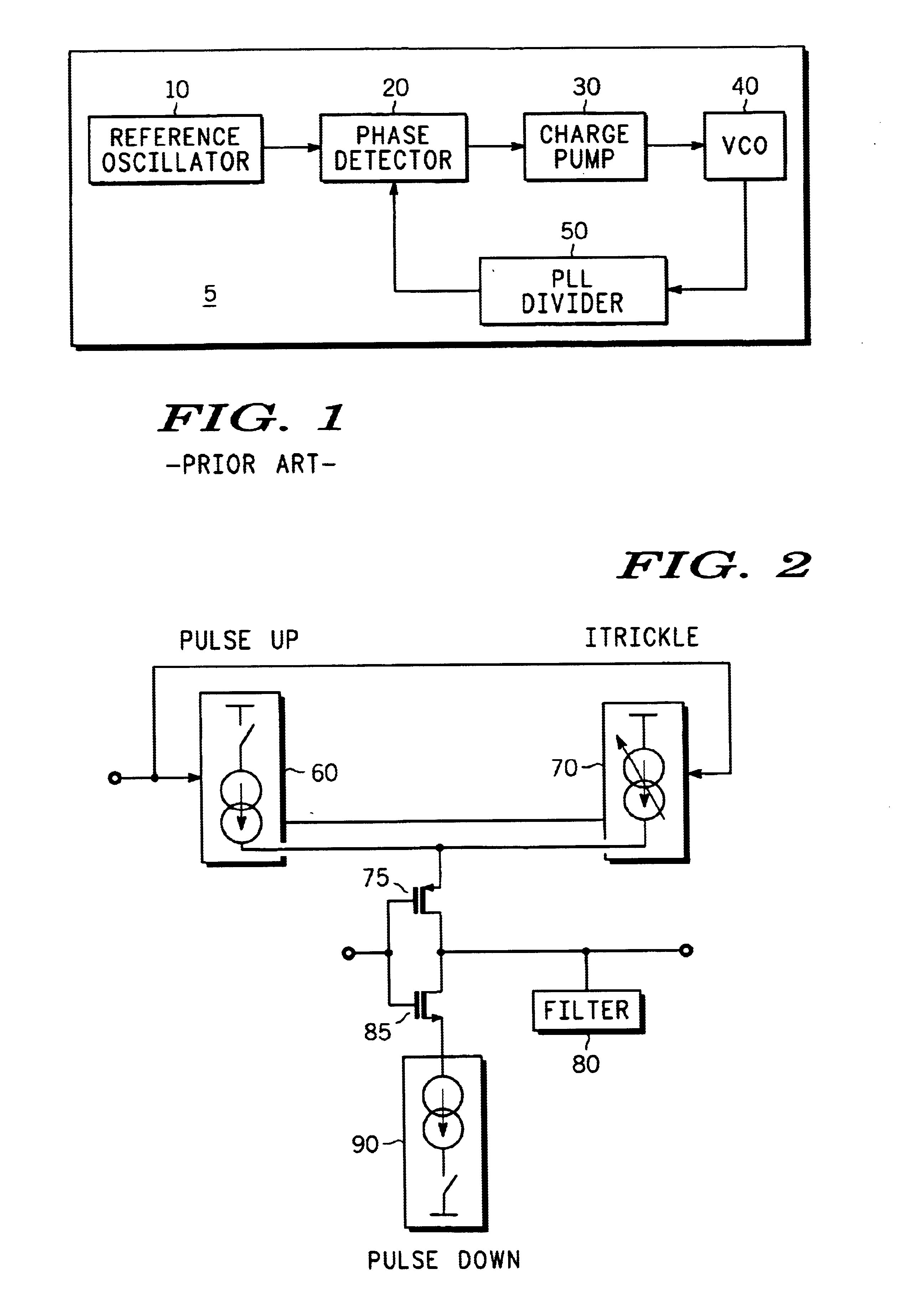
Referring to FIG. 1, there is shown a prior art Phase-Locked-Loop (PLL) arrangement 5, incorporating a charge pump 30.

A reference oscillator 10 provides a reference AC voltage to the charge pump 30 via a phase detector 20. An output of the charge pump 30 is coupled to a VCO 40.

A PLL divider 50 is coupled to receive an output from the VCO 40, and is further coupled to provide an output to the phase detector 20, providing a feedback loop.

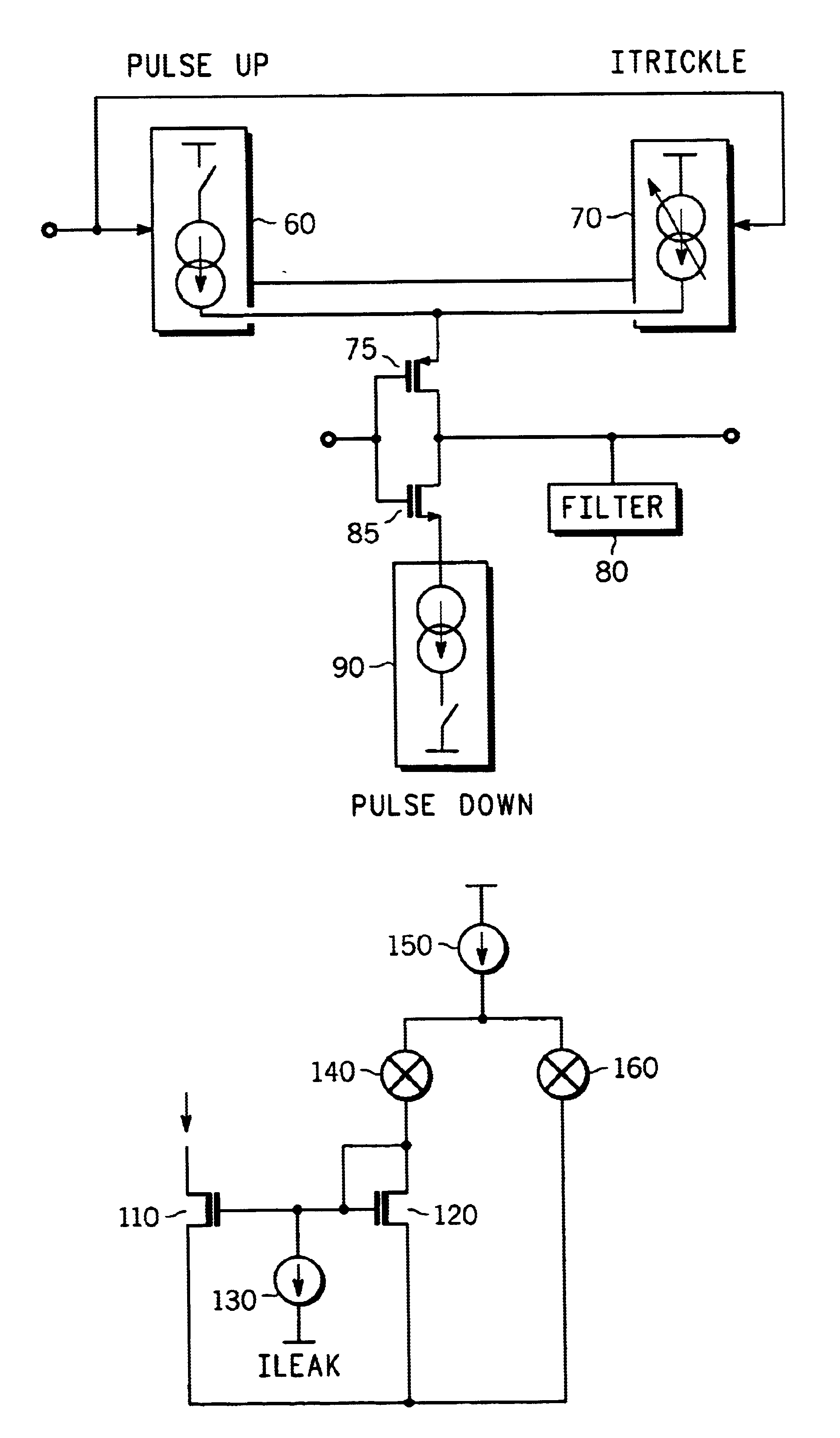
Referring now also to FIG. 2, there is shown a detailed block diagram of a high voltage charge pump in accordance with a preferred embodiment of the present invention, to be used in place of a typical charge pump, in a PLL arrangement such as that of FIG. 1. The charge pump includes a `Pulse Up` block 60, a `Pulse Down` block 90, an `Itrickle` block 70 and first and second Field Effect Transistors (FETs) 75 and 85 respectively, to be further described below. It should be noted that the filter block 80 is not part of the charge pump but a component of...


PUM


Abstract

A charge pump arrangement for a phase-locked-loop has a current source circuit (60) which provides charging current to the phase locked loop, and a current sink circuit (90) which depletes charging current from the phase locked loop. The current source circuit (60) and the current sink circuit (90) have slew rates which have a predetermined relationship. In this way, the charge pump causes substantially no non-linear charge injection in the phase-locked-loop. Cascoded current mirrors (75, 85) are utilised to provide a high voltage with thin gate oxide technology. The arrangement has a relatively small die size. Since bias currents of the arrangement are mirrored according to the output current required, improved transient times are produced, leading to reduced phase noise.

Description

This invention relates to charge pumps that are used in PLLs (Phase Locked Loops) for applications such as frequency synthesis / clock generation.In the field of this invention it is known that for Fractional N (FRAC-N) PLL arrangements, linearity of the associated charge pump is a key requirement. A major problem in the circuit design of such charge pumps is achieving a required level of linearity around the "lock" condition.The nature of PLL modulation during the "lock" condition requires that extra charge is added or taken out of the loop filter, the charge being proportionate to the modulation.In the case of a mobile cellular telecommunications device arranged to transmit using a direct digital modulation technique and using a PLL as described above, the tuning line voltage of a Voltage Controlled Oscillator (VCO) of the device is modulated, which in turn causes Frequency Modulation (FM) on a transmit (or TX) output of the device. Non-linearity of the PLL in this arrangement leads...

Claims


Application Information

Patent Timeline
08 Jun 2004
Publication
US6747494B2
IPC
H03L7/089; H03L7/08
CPC
H03L7/0895
Inventors
BUSHEY, THOMAS P.; MOORE, JEREMY W