Visual inspection and verification system

a verification system and visual inspection technology, applied in the field of integrated circuit manufacturing, can solve the problems of inability to accurately measure the printability of potential mask defects and/or the overall mask quality assessment of mask inspection systems

Inactive Publication Date: 2004-06-29
SYNOPSYS INC
View PDF56 Cites 212 Cited by
  • Summary
  • Abstract
  • Description
  • Claims
  • Application Information

AI Technical Summary

Benefits of technology

In still another embodiment of the present invention, the apparatus includes a defect analyzer which analyzes the first simulated image for defects on the mask. The defect analyzer may generate a process window related output, an analysis output comprising a signal which indi...

Problems solved by technology

As discussed above, currently known mask inspection systems are not capable of providing an accurate measure of the printability of a...

Method used


Image

  • Visual inspection and verification system
  • Visual inspection and verification system
  • Visual inspection and verification system

Examples


Embodiment Construction

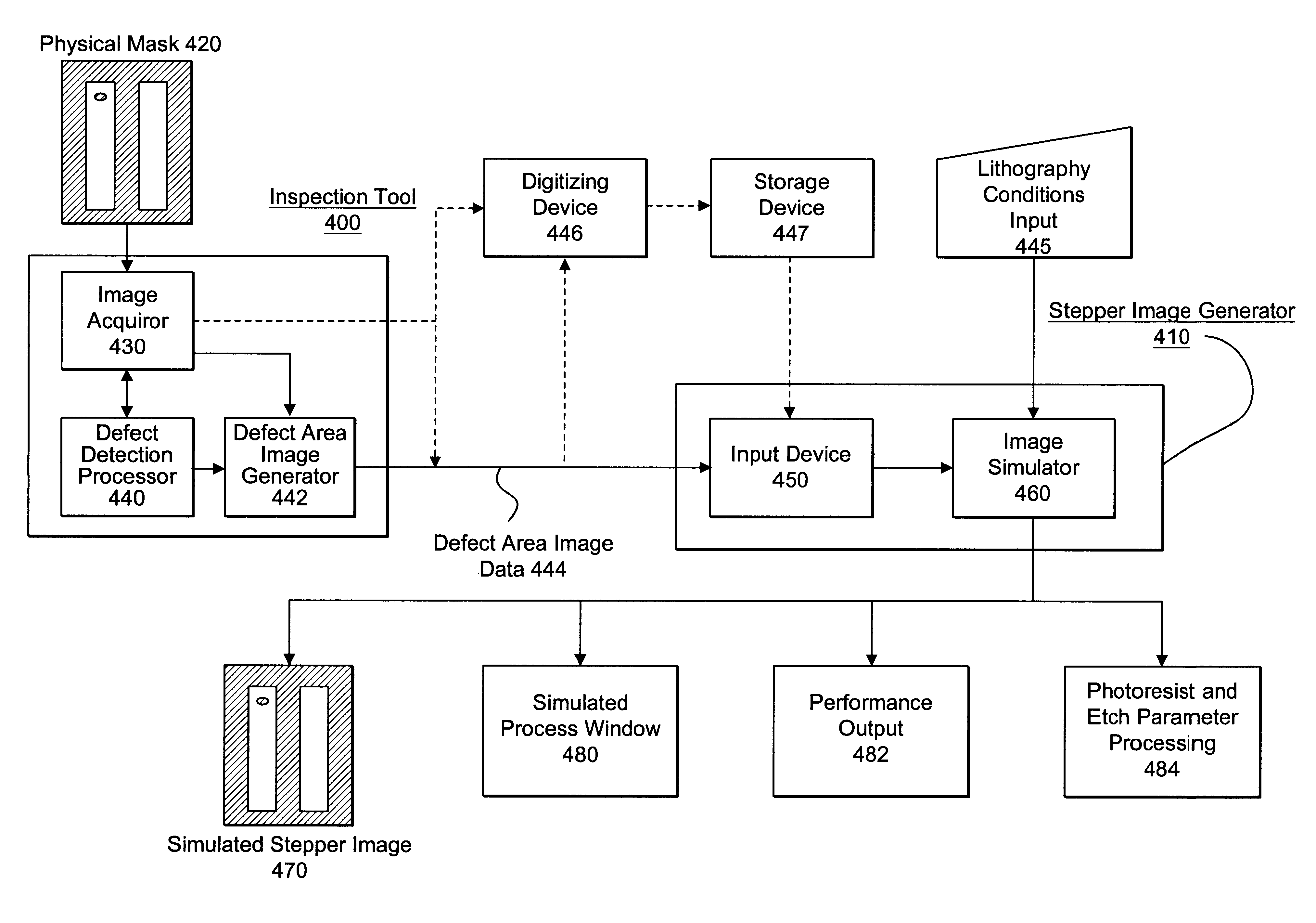
Photolithography is a process whose input is a mask and whose output is the printed patterns on a wafer. The printed result from a mask is what design engineers, lithographers, and mask manufacturers really care about. Using prior methods, the only way to inspect this printed result was to perform an actual wafer exposure and therefore incur potentially unnecessary costs in time and money. The present invention solves some of the problems of these prior methods by providing for mask inspection that takes printability into account without the need for the expensive steps of actually exposing a wafer. The present invention is capable of using a captured image of a mask--that accurately enough represents the physical mask (i.e. such as from a high resolution optical microscope or a scanning electron microscope)--and using that captured image to simulate the wafer exposure that the mask would provide under a given set of stepper conditions. Thus, when an initial mask inspection for defe...


PUM


Abstract

A method and apparatus for inspecting a photolithography mask for defects is provided. The inspection method comprises providing a defect area image to an image simulator wherein the defect area image is an image of a portion of a photolithography mask, and providing a set of lithography parameters as a second input to the image simulator. The defect area image may be provided by an inspection tool which scans the photolithography mask for defects using a high resolution microscope and captures images of areas of the mask around identified potential defects. The image simulator generates a first simulated image in response to the defect area image and the set of lithography parameters. The first simulated image is a simulation of an image which would be printed on a wafer if the wafer were to be exposed to an illumination source directed through the portion of the mask. The method may also include providing a second simulated image which is a simulation of the wafer print of the portion of the design mask which corresponds to the portion represented by the defect area image. The method also provides for the comparison of the first and second simulated images in order to determine the printability of any identified potential defects on the photolithography mask. A method of determining the process window effect of any identified potential defects is also provided for.

Description

THE BACKGROUND OF THE INVENTIONa. The Field of the InventionThis invention relates to the field of integrated circuit manufacturing. In particular, the invention relates to a system for inspection of defects on masks used in the manufacture of integrated circuits.b. Description of Related ArtIn designing an integrated circuit (IC), engineers typically rely upon computer simulation tools to help create a circuit schematic design consisting of individual devices coupled together to perform a certain function. To actually fabricate this circuit in a semiconductor substrate the circuit must be translated into a physical representation, or layout, which itself can then be transferred onto a template (i.e., mask), and then to the silicon surface. Again, computer aided design (CAD) tools assist layout designers in the task of translating the discrete circuit elements into shapes which will embody the devices themselves in the completed IC. These shapes make up the individual components of ...

Claims


Application Information

Patent Timeline
IPC IPC(8): G03F7/20G03F1/00G06F17/50G03F7/14G01Q30/02G01Q30/04G01Q60/18G01Q60/24G01Q80/00G01Q90/00G03F1/26G03F1/36G03F1/84G06T7/00H01L21/027
CPCG03F1/26G03F1/84G03F7/70441G03F7/705G06F17/5068G06T7/0004G03F1/36G06T2207/30148G06F30/39G06F18/00
Inventor CHANG, FANG-CHENGWANG, YAO-TINGPATI, YAGYENSH C.KARKLIN, LINARD N.
Owner SYNOPSYS INC
Why Eureka
Try Eureka