
Radio transmitter-receiver, high-frequency radio receiver, and control unit

a transmitter receiver and radio receiver technology, applied in power management, wireless communication, high-level techniques, etc., can solve the problems of accelerating the deterioration of the receiving characteristics, affecting the operation of the cdma mobile terminal apparatus, and reducing the unnecessary current consumption of the transmitting radio-frequency circuit, so as to prevent the variation of the frequency characteristics of the front-stage circuit and reduce the effect of unnecessary current consumption

Inactive Publication Date: 2004-07-20
GK BRIDGE 1
View PDF23 Cites 20 Cited by
  • Summary
  • Abstract
  • Description
  • Claims
  • Application Information

AI Technical Summary

Benefits of technology

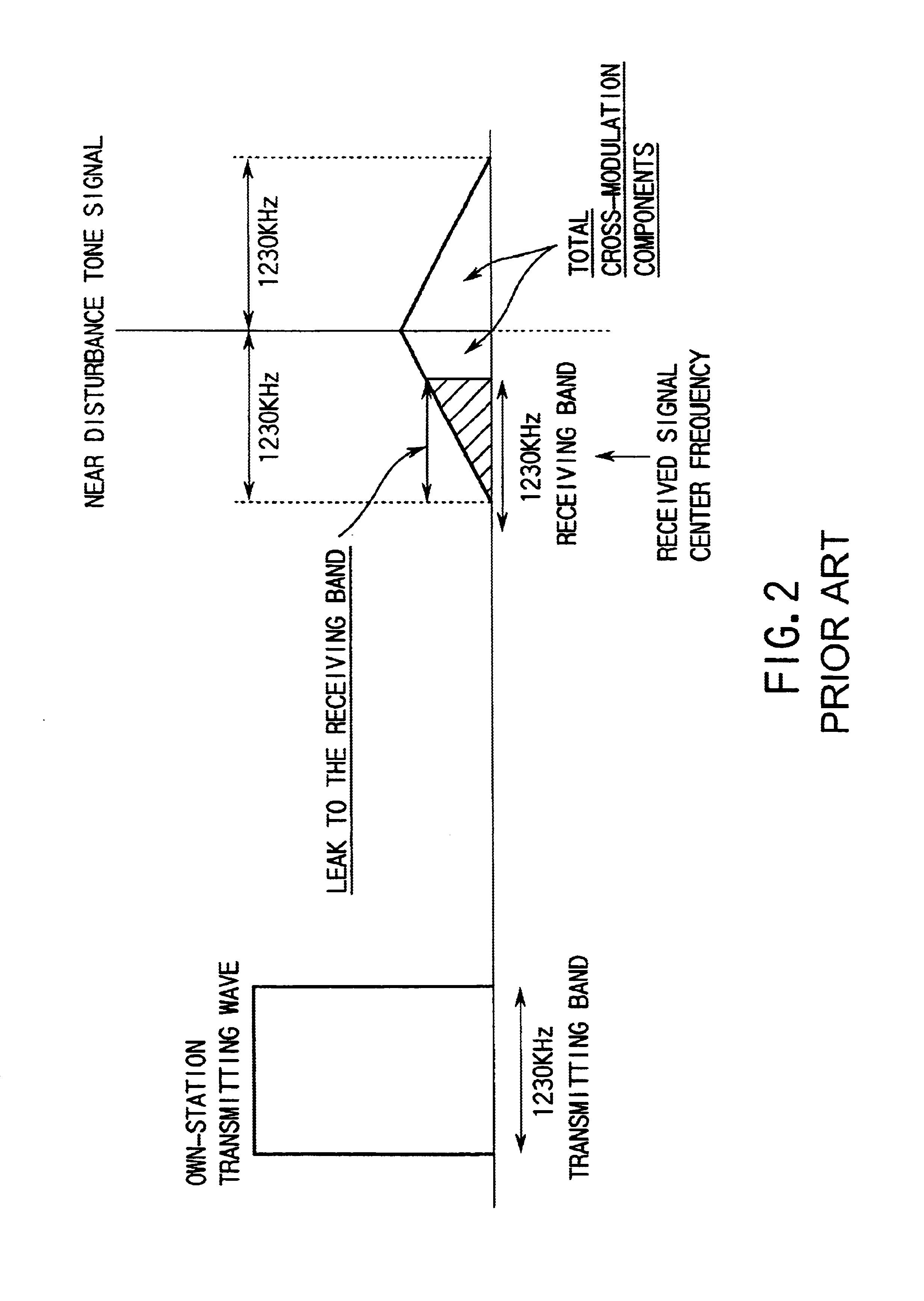
Therefore, according to the present invention, since the receiving radio-frequency unit is operated in the low-distortion mode, in the period in which the radio signal is transmitted, the deterioration of the receiving sensitivity which is caused by the interference to the receiving band resulting from the cross modulation between the near disturbance wave of the desired receiving wave and its own transmitting wave, is suppressed, and the receiving distortion characteristics can be thereby kept preferable.
Further, in the radio transmitter-receiver employing the open-loop control of the transmitting level, where variation components caused by changing of the modes of the receiving radio-frequency unit, that is, changing of the active circuit and changing of the supply of the bias current is generated in the transmitting level control signal generated on the basis of the output signal level of the receiving radio-frequency unit during the above-mentioned open-loop transmission control, the variation components may be canceled by the variation suppressing means. With this structure, the variation in the transmitting level resulting from the gain variation of the active circuit in the receiving radio-frequency unit can be canceled, which allows the transmitting level error of the upstream radio signal to be reduced and also allows unnecessary current consumption in the transmitting radio-frequency circuit to be reduced.

Problems solved by technology

When the mobile terminal apparatus exists in a place where the received signal level is low, such a case where the mobile terminal apparatus exists in, for example, a fringe area of a cell, deterioration of the receiving characteristics is accelerated because of the interference caused by the cross modulation effect, which may cause the communications to be interrupted in a worst case.
In order to implement this, however, the consumed current needs to be increased to about 10 to about 20 [mA], and this will cause the standby time of the CDMA mobile terminal apparatus to be made remarkably shorter, which is not very preferable.
With these measures, however, the duplexer is excessively large, which may disturb miniaturization of the mobile terminal apparatus and the reduction of the weight thereof.

Method used


Image

  • Radio transmitter-receiver, high-frequency radio receiver, and control unit
  • Radio transmitter-receiver, high-frequency radio receiver, and control unit
  • Radio transmitter-receiver, high-frequency radio receiver, and control unit

Examples


first embodiment

(First Embodiment)

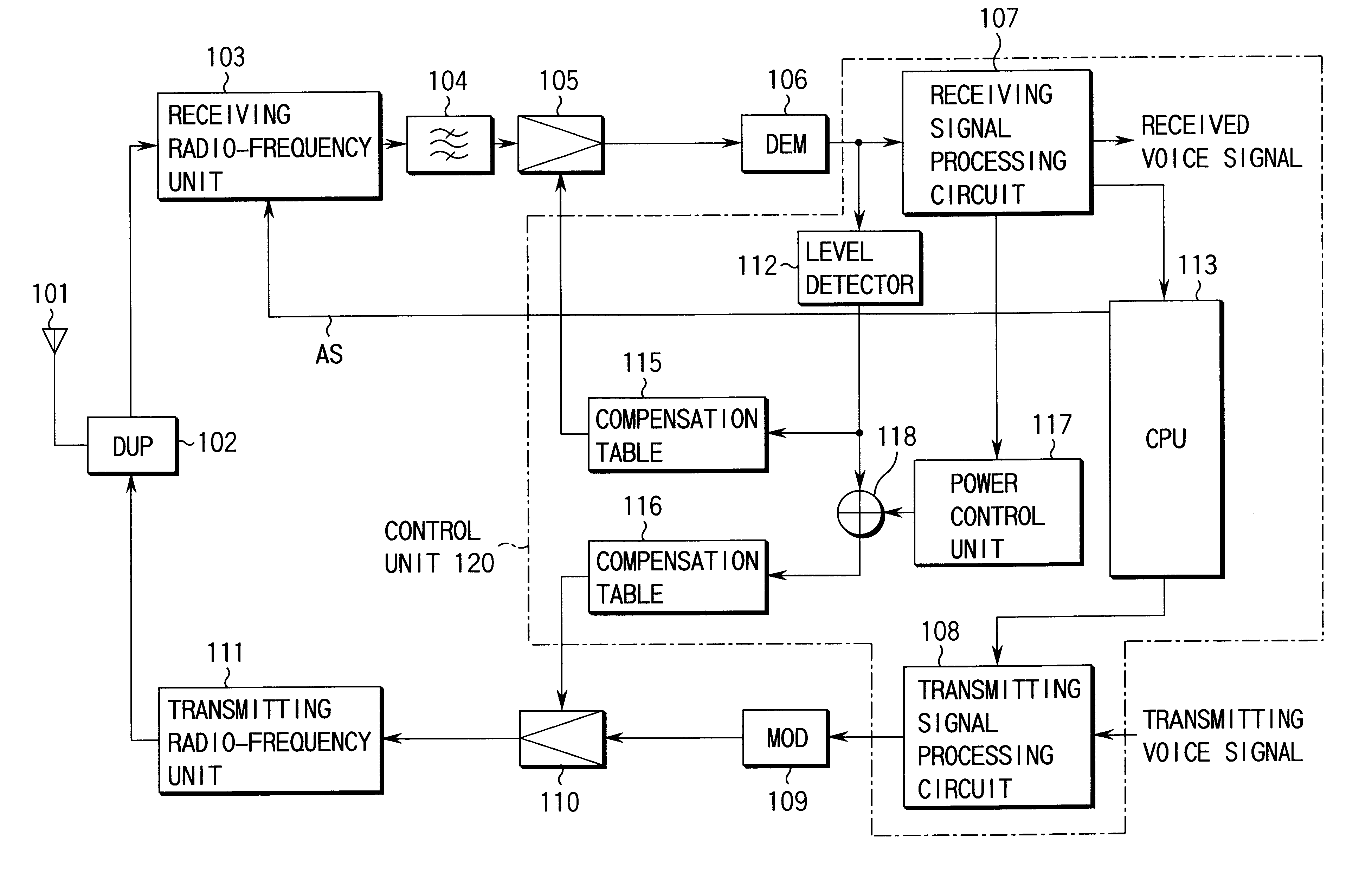
FIG. 3 is a block diagram showing a CDMA radio transmitter-receiver for a mobile terminal apparatus, according to a first embodiment of the present invention.

In the figure, a radio frequency signal transmitted from a base station (not shown) is received by an antenna 101, and input to a receiving radio-frequency unit 103 serving as a receiving front end stage via a antenna duplexer (DUP) 102. In the receiving radio-frequency unit 103, the received radio frequency signal is subjected to the low noise amplification, removal of received unnecessary waves outside the receiving band, and frequency conversion into the receiving intermediate frequency. Unnecessary waves near desired signals are removed from the receiving intermediate frequency signal by an intermediate frequency filter 104. Further, the receiving intermediate frequency signal is adjusted to be a signal level suitable for the demodulating process of a latter stage by a receiving variable-gain amplifier 105...

second embodiment

(Second Embodiment)

According to a second embodiment of the present invention, when the apparatus has a transmitting mode for intermittently burst-transmitting a transmitting radio wave in accordance with the transmission bit rate, switching between the low distortion LNA and the low current consumption LNA in the receiving radio-frequency unit is executed by using a transmission timing control signal which is output to the transmitting radio-frequency circuit by the control unit, for the intermittent transmission control.

FIG. 5 is a block diagram showing a configuration of a radio transmitter-receiver according to a second embodiment. In this figure, the same portions as those of FIG. 3 are denoted by the same reference numerals, and their explanation is omitted.

Generally, a CDMA radio transmitter-receiver provides the variable rate coding for varying the encoding rate in accordance with the state of a speaker's voice, for example, whether a speaker speaks fast or slowly, whether du...

third embodiment

(Third Embodiment)

A third embodiment of the present invention is an improvement of the above-described second embodiment. The receiving level of the downstream radio signal transmitted from the base station is determined by using the gain control signal for the open-loop transmission power control. The low distortion LNA is selected during the upstream radio signal burst-transmitting period and in a case where the receiving level of the downstream radio signal is lower than a threshold value. On the other hand, even in the upstream radio signal burst-transmitting period, when the receiving level of the downstream radio signal is equal to or higher than a threshold value, the receiving radio-frequency unit is switched so as to select the low current consumption LNA.

FIG. 6 is a block diagram showing a radio transmitter-receiver according to the third embodiment. In this figure, the same portions as those shown in FIG. 5 are denoted by the same reference numerals and their detailed exp...


PUM


Abstract

A low-noise amplifier 500a having low-distortion characteristics (low distortion LNA), a low-noise amplifier 500b of a low current consumption type(low current consumption LNA), and radio-frequency switches 502 and 509 for selectively switching either of them are provided in a receiving radio-frequency unit 103. On the basis of a mode changing control function of a CPU 113, an LNA switch control signal AS is generated so that the low-distortion LNA 500a is selected during a period in which the operation of a radio transmitter-receiver is in a transmitting / receiving state, and that the low current consumption LNA 500b is selected in a period of a standby state, and thus the switching of the radio-frequency switches 502 and 509 of a low-noise amplifier circuit section 501 is controlled.

Description

The present invention relates to a radio transmitter-receiver of so called a simultaneous transmitting and receiving system, capable of receiving a downstream radio signal transmitted from a base station while transmitting an upstream radio signal having amplitude variation components, such as a mobile terminal apparatus employing the CDMA (Code Division Multiple Access) scheme.Recently, a cellular radio communications system has been rapidly widespread in accordance with the increase in the needs for the mobile communications and the development of the communications techniques.A mobile terminal apparatus used in the cellular radio communications system, for example, receives a radio frequency signal transmitted from a base station, by an antenna, inputs the signal to a receiving radio-frequency unit via an antenna duplexer, high-frequency-amplifies the signal, removes unnecessary waves outside the receiving band from the signal, converts the signal to an intermediate frequency sig...

Claims


Application Information

Patent Timeline
Patent Type & Authority Patents(United States)
IPC IPC(8): H04B1/16H04B1/10H04B1/3822H04B1/40
CPCH04B1/109H04B1/1615H04W52/0229Y02D30/70
Inventor HAYASHIHARA, MIKIO
Owner GK BRIDGE 1
Learn More