

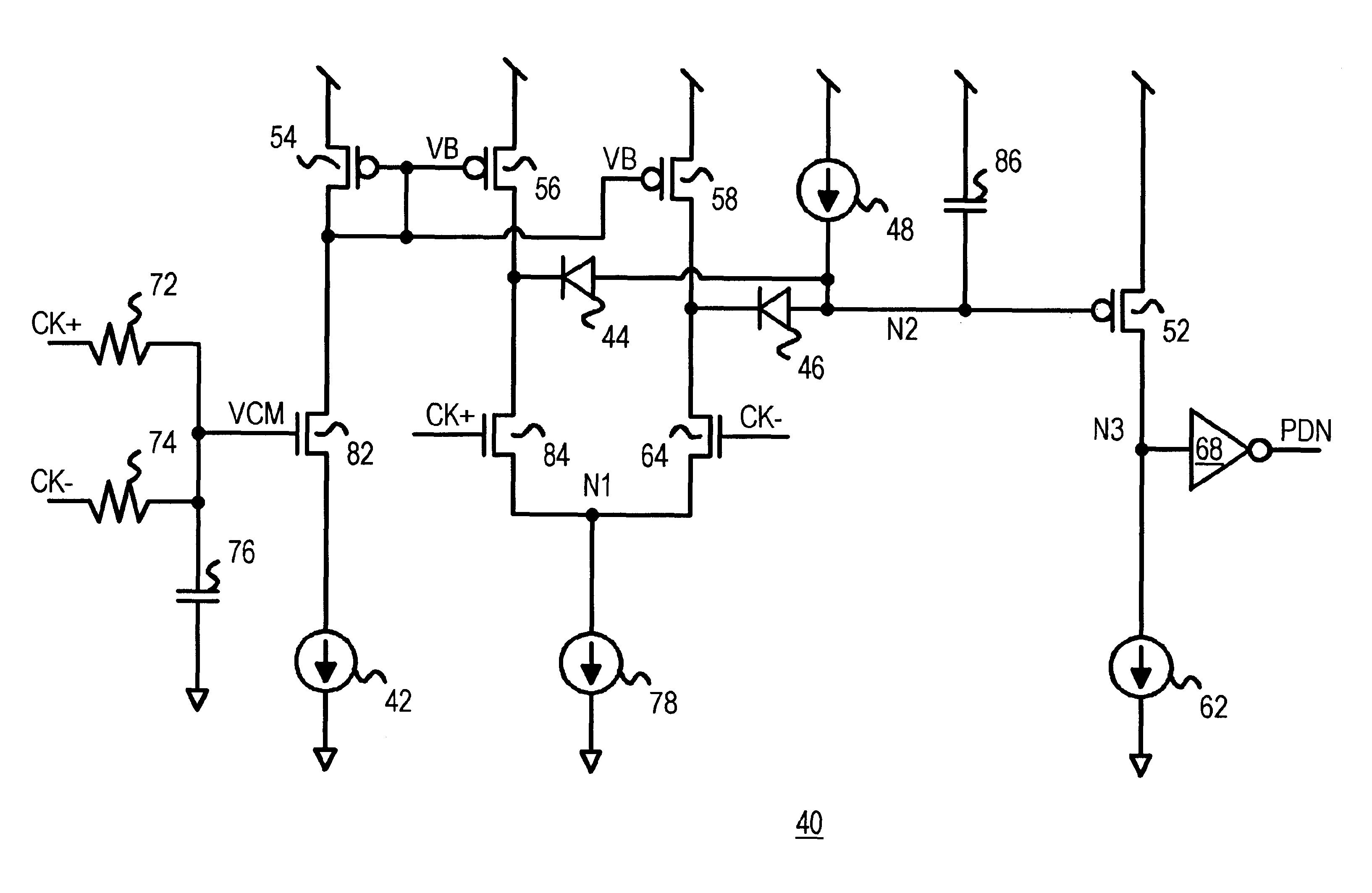
Clock presence detector comparing differential clock to common-mode voltage
a detection device and clock technology, applied in the field of clock detection, can solve the problems of abnormal or illegal high-high condition, system not in continuous use, and limited number of available pins on the integrated circuit chip
- Summary
- Abstract
- Description
- Claims
- Application Information
AI Technical Summary
Benefits of technology
Problems solved by technology
Method used
Image

Examples
Embodiment Construction
Several other embodiments are contemplated by the inventor. For example the shunt resistor between the CK+ and CK- line may not be present in some embodiments but not other embodiments. Resistor loads could replace transistor-based current sources and sinks. Negative current can reverse the meaning of sink and source.
Other devices such as additional gates, inverters, buffers, resistors, and capacitors can be added. Many other applications are possible, such as memory module power-down, powering down a network card, wireless subsystems, display systems, etc., in PC or other systems.
The power-down signal may be driven off the receiver chip to other chips such as memory chips on a memory module. The envelope detector could be integrated with the differential receiver and the circuits to be powered down, or it could be separate from either or both of the differential receiver and the powered-down circuits. The power-down signal may not be used for power-down purposes, but may be a clock...
PUM
 Abstract
Description
Claims
Application Information