Variable gain low noise amplifier

Inactive Publication Date: 2004-11-16
AGENCY FOR SCI TECH & RES
View PDF9 Cites 25 Cited by
  • Summary
  • Abstract
  • Description
  • Claims
  • Application Information

AI Technical Summary

Problems solved by technology

The problem of gain control versus the noise figure (NF) of low noise amplifiers as frequencies g

Method used


Image

  • Variable gain low noise amplifier
  • Variable gain low noise amplifier
  • Variable gain low noise amplifier

Examples


Embodiment Construction

Embomdiment

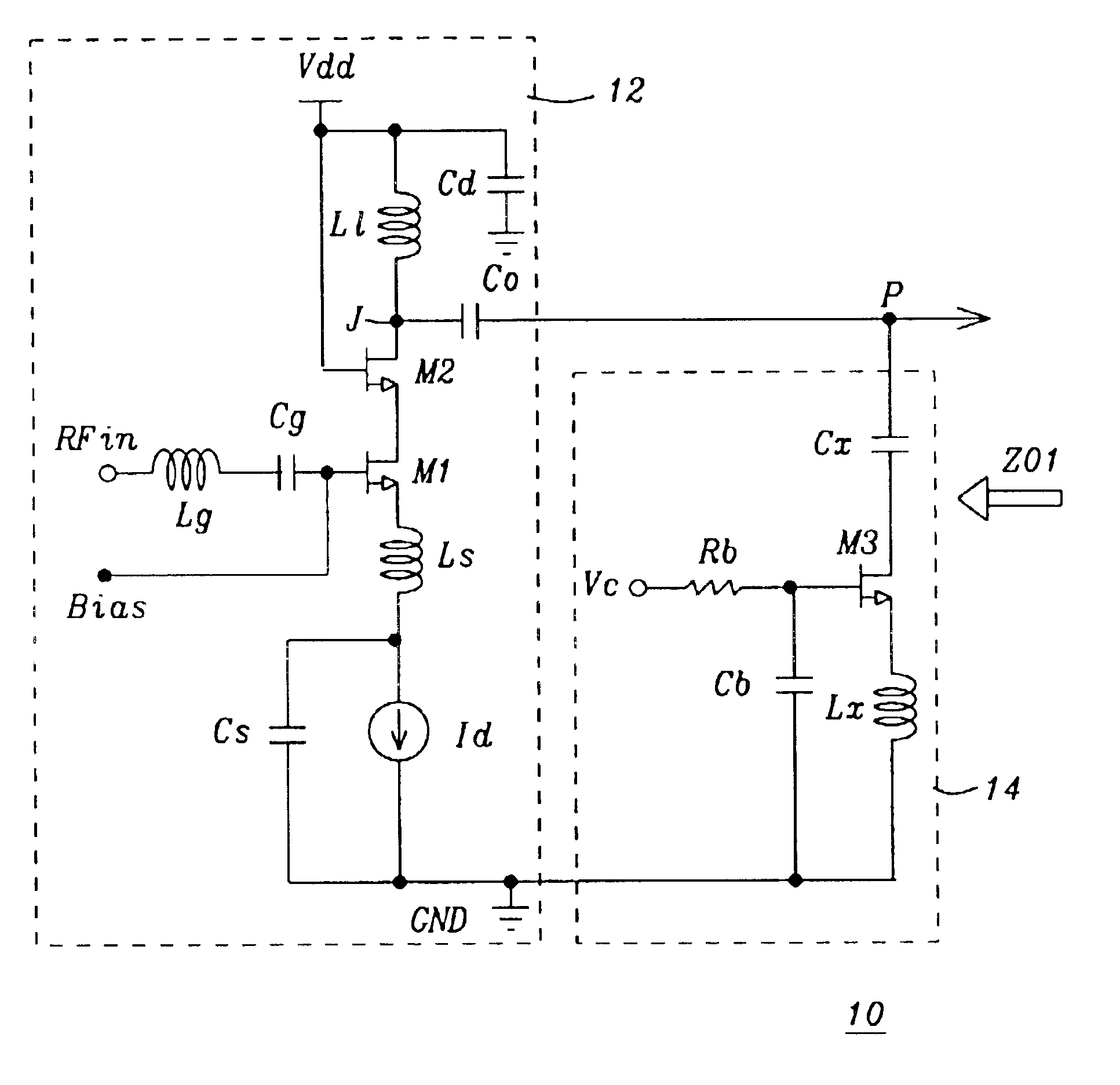
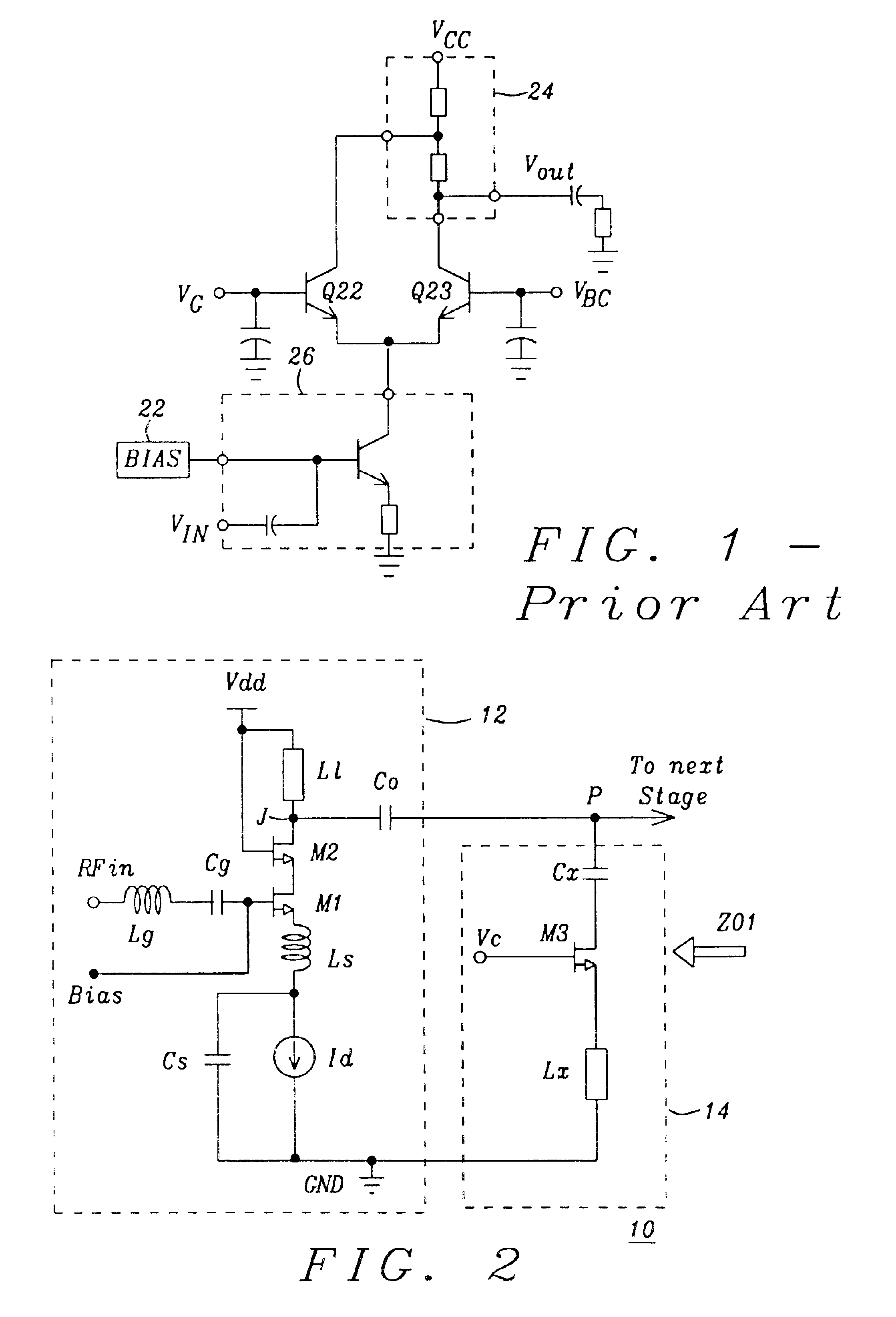
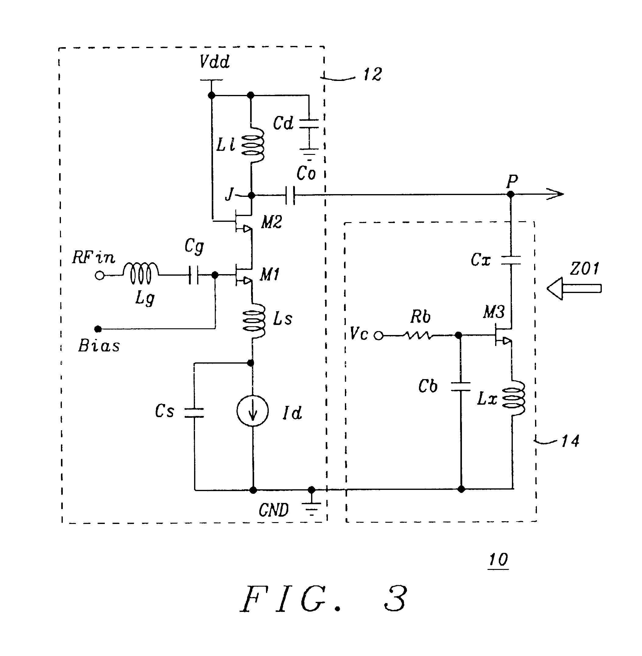
FIG. 3 shows a Variable Gain LNA 10 in one of its simple forms. FIG. 3 is similar to FIG. 2, except that a) a decoupling capacitor C.sub.D is coupled between Vdd and ground, b) loads L.sub.L and Lx are shown as inductors, c) resistive means Rb is coupled between the gate of M3 and Vc, and c) capacitor Cb is coupled between the gate of M3 and ground.

The LNA is matched to the input impedance through Lg, Ls and the gate-to-source capacitance Cgs (not shown) of M1 for the desired frequency band of operation. Capacitor Cs is used to provide RF ground to Ls. Transistors M1 (Common Source) and M2 (Common Gate) form the cascode amplifier. Cd is the decoupling capacitor. Inductive Load L.sub.L is used rather than a resistive load as the inductive load offers lower NF and better IIP3. The overlap transistor gate-to-drain capacitance Cgd (not shown) of M2 and the load inductance L.sub.L determine the output impedance Z.sub.O1. Usually the input impedance of the following stage is op...


PUM


Abstract

The load of the cascode amplifier is varied by connecting another (secondary) load in parallel with the original load. The secondary load is connected through a MOSFET switch. During the High Gain Mode the MOSFET switch is OFF and the secondary load is electrically isolated from the main load, whereas in the Low Gain Mode the switch is turned ON and the secondary load appears across the primary load, reducing the effective load impedance. The secondary load is AC coupled such that the DC bias current does not pass through the secondary load and hence the Noise Figure (NF) and linearity (IIP3) performance are better in the Low Gain Mode. A number of such switchable loads can be connected across the load to obtain programmability.

Description

1. Field of the InventionThis invention relates generally to the control of the gain of amplifiers or other high frequency blocks such as filter attenuators etc., by switching the load impedance. The invention in particular relates to controlling the gain of a Low Noise Amplifier (LNA).2. Description of the Related ArtThe problem of gain control versus the noise figure (NF) of low noise amplifiers as frequencies go steadily higher in the Giga Hertz range is a continuing challenge to all workers in this field. We now describe a circuit of the related art by referring to FIG. 1. FIG. 1 is taken from U.S. Pat. No. 6,046,640 (Brunner), discussed below, and is referred there to as FIG. 6. The circuit is a switched-gain cascode amplifier, including an input stage 26, a loading network 24, first and a second cascode transistors Q22, Q23, and a bias signal generator 22. The input stage 26 receives a bias signal V.sub.BIAS and the input signal V.sub.IN. The loading network 24 is coupled to a...

Claims


Application Information

Patent Timeline
IPC IPC(8): H03F1/08H03G1/00H03G3/00H03F1/32H03F1/22H03F1/26H03F3/195H03F3/72
CPCH03F1/223H03F1/26H03F1/32H03F3/195H03F3/72H03G3/001H03G1/0088H03F2200/294H03F2200/372H03F2200/421H03F2200/501H03F2200/243
Inventor RAJA, MUTHUSAMY KUMARASAMYMANIAM, NUNTHA KUMAR KRISHNASAMY
Owner AGENCY FOR SCI TECH & RES
Why Eureka
Try Eureka