
Electrically sensing and stimulating system for placement of a nerve stimulator or sensor

a nerve stimulator and sensing technology, applied in the field of electric sensing and stimulating system for placement of nerve stimulators or sensors, can solve the problems of increasing power requirements, imposing risk, discomfort and potential tissue damage on patients, and no way to detect the movement of cannulas, so as to facilitate the placement of microstimulators in living tissu

Inactive Publication Date: 2004-12-07
ALFRED E MANN FOUND FOR SCI RES
View PDF18 Cites 286 Cited by
  • Summary
  • Abstract
  • Description
  • Claims
  • Application Information

AI Technical Summary

Benefits of technology

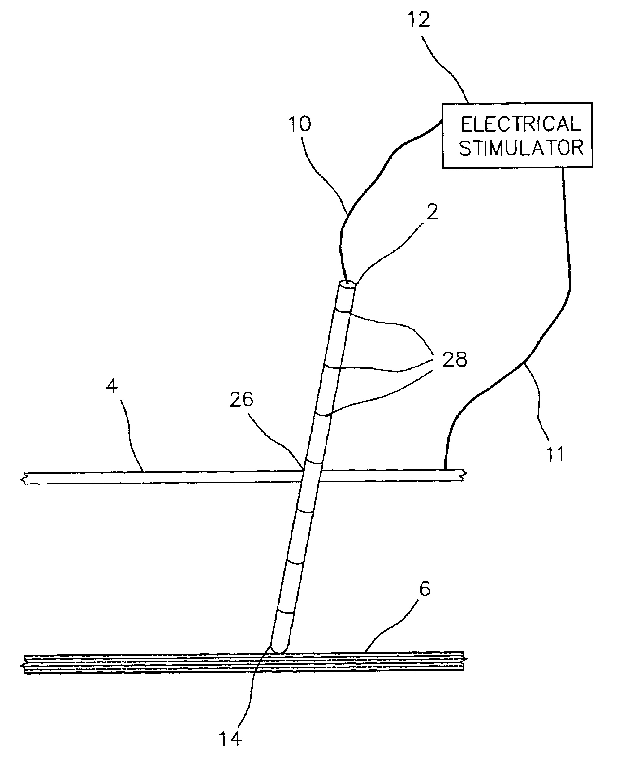
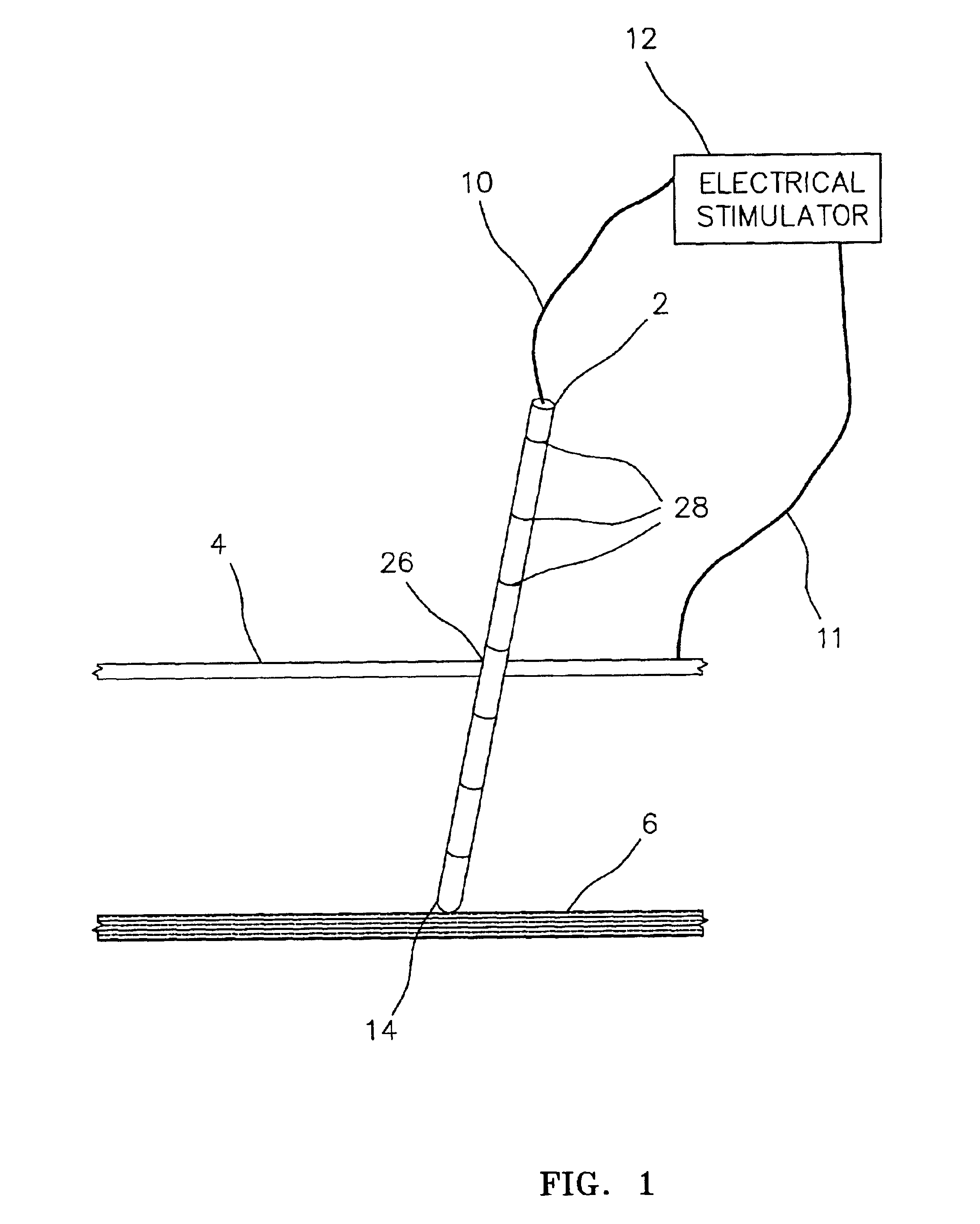
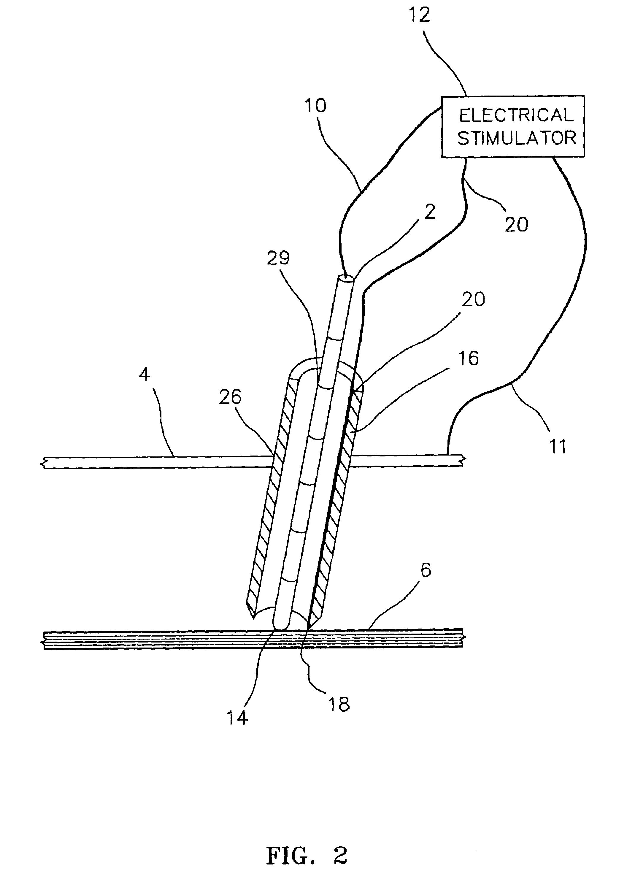
This device offers the additional improved feature that both the outer sheath 16 and the inner sheath 8 are near the nerve 6, thus allowing the ultimate position of the implanted microdevice to be near the nerve 6. The closer the implanted microdevice is to the nerve, generally, the less power is consumed in its operation and the longer the device will survive without battery replacement.
In a preferred embodiment, the microstimulator 22 (see FIG. 13) contains removal loop 30, e.g., an eyelet, on the end nearest the skin 4 to facilitate attachment of removal string 32 to the microstimulator 22. The removal string 32 may be left in the living tissue near the insertion point 26 (see FIG. 14) or it may be left outside the living tissue. The removal string may be used to locate and / or to remove the microstimulator by pulling on it. This technique is effective for a few days post-surgery to remove the microstimulator 22 without risking further damage or trauma to the implant area, until the tissue begins to heal and adheres to the microstimulator.
Saline is preferably injected into the implantation tool 300. The saline facilitates obtaining a good electrical connection between the nerve, living tissue, and the microstimulator 322 which is about to be implanted. In a preferred embodiment (see FIG. 20), the microstimulator 322 has microstimulator electrodes 323 located on each end.
FIG. 22 depicts an alternative embodiment of the invention wherein there is a ring electrode 418 that is attached circumferentially at the sharpened tip of outer sheath 416 that is nearest the nerve 406. The outer sheath 416 passes through the skin 404 at the insertion point 426. The outer sheath 416 contains holes 417 which are located in the wall of the outer sheath 416 to facilitate electrical contact between the microstimulator (not shown) and the living tissue during insertion of the microstimulator in the tissue, but before the microstimulator has been ejected from the outer sheath 416. An electrical signal is generated by the electrical stimulator 412 that passes along sheath lead wire 420 to ring electrode 418. Ring electrode 418 is a conductive material that may be plated, deposited, mechanically bonded, or attached by any of the known processes for making a conductor that is integrally bonded to or a part of the sharpened tip of outer sheath 416. The sharpened tip end (i.e., inserted end) is referred to as the distal end of the outer sheath 416, while the opposite end of the outer sheath 416 is referred to as the proximal end. An advantage of having a ring electrode 418 over a single point electrode is that the possibility of damaging the nerve 406 with an electric pulse is reduced when the size of the electrode is increased.
A benefit of utilizing the ring electrode 418 in conjunction with the ring return electrode 422 is that by locating ring return electrode 422 a distance from ring electrode 418 that approximates the distance between the electrodes on the microstimulator (not illustrated), the electrical resistivity that the microstimulator will encounter after being implanted in the living tissue can be measured before the microstimulator is ejected from the outer sheath 416. This allows a prediction of the battery life of the implanted microstimulator and gives the surgeon an opportunity to modify the implantation location, if the predicted life or performance of the microstimulator is not adequate.

Problems solved by technology

If there is a problem with the function or location of the microstimulator, then additional surgery must be performed to remove or relocate the microstimulator, imposing risk, discomfort and potential tissue damage to the patient.
The problem is that once the electrically stimulating trocar is removed, there is no way to detect movement of the cannula.
This displacement from the optimum stimulating site unacceptably increases the power requirements and diminishes the battery life of the microstimulator.

Method used


Image

  • Electrically sensing and stimulating system for placement of a nerve stimulator or sensor
  • Electrically sensing and stimulating system for placement of a nerve stimulator or sensor
  • Electrically sensing and stimulating system for placement of a nerve stimulator or sensor

Examples


Embodiment Construction

Microstimulator Implantation Procedure, Anterior Approach, for Sleep Apnea

1. Instruct the patient to lie down in the supine position.

2. Prepare the patient for surgery using standard surgical preparation.

3. Anesthetize the skin and subcutaneous tissue with 1% xylocaine / 1:100,000 epinephrine at and around the insertion site in the neck.

4. Anesthetize one nostril and the nasopharynx with topical lidocaine / oxymetazoline solution and insert a laryngoscope to observe tongue movement during hypoglossal nerve stimulation.

5. Mark the midpoint of the hyoid bone and mark a point about 1 cm anterior / superior to the hyoid with a sterile pen. Make an incision about 1 cm wide parallel to the hyoid extending down into the subcutaneous tissue about 5 mm mid center over the 1 cm anterior point. Use an intravenous sedative as required.

6. Attach the electrical stimulator cathodal connecting lead to the proximal end of the blunt tipped electrode probe. The electrical stimulator anode lead is attached t...


PUM


Abstract

An electrically sensing and stimulating outer sheath for ensuring accurate surgical placement of a microsensor or a microstimulator near a nerve in living tissue is disclosed. The electrically sensing outer sheath may also be used to verify the function of the microstimulator or microsensor during surgical placement but before the outer sheath is removed. In the event that the microstimulator is not optimally placed near the nerve, or if the microstimulator is malfunctioning, this can be determined prior to removal of the outer sheath, thus reducing the possibility of nerve or tissue damage that might be incurred during a separate operation to remove the microstimulator.

Description

This invention relates to placement of a nerve stimulator or sensor in living tissue.Microstimulators are small, implantable electrical devices that pass a small signal to living tissue in order to elicit a response from a nerve or muscle. Microsensors are similar electrical devices except that they detect electrical and other signals that are generated by living tissue. The term microstimulator is intended to apply equally to both microstimulators and microsensors. The use of microstimulators or microsensors which are implanted in living tissue to stimulate a muscle function by either stimulating a nerve or the muscle itself are well known. The microstimulators receive power and control signals by inductive coupling of magnetic fields generated by an extracorporeal antenna rather than requiring any electrical leads. See for example, U.S. Pat. Nos. 5,193,539; 5,193,540; 5,324,316; 5,405,367; 6,175,764; 6,181,965; 6,185,452; 6,185,455; 6,208,894; 6,214,032; and 6,315,721, each of whi...

Claims


Application Information

Patent Timeline
IPC IPC(8): A61N1/36A61N1/05A61N1/18A61B5/05A61N1/08
CPCA61N1/08A61N1/0551A61B17/3468
Inventor SCHULMAN, JOSEPH H.WEISNER, RALPH M.CANFIELD, DAVID L.FEY, KATE E.BYERS, CHARLES L.
Owner ALFRED E MANN FOUND FOR SCI RES
Learn More