

Bearing assembly with electric power generator
a technology of bearing assembly and generator, which is applied in the direction of machines/engines, mechanical circuit shapes/forms/construction, instruments, etc., can solve the problems of difficulty in obtaining electric power, large size, and complicated assemblage, and achieve the effect of sufficient sealability
- Summary
- Abstract
- Description
- Claims
- Application Information
AI Technical Summary
Benefits of technology
Problems solved by technology
Method used
Image

Examples
first embodiment
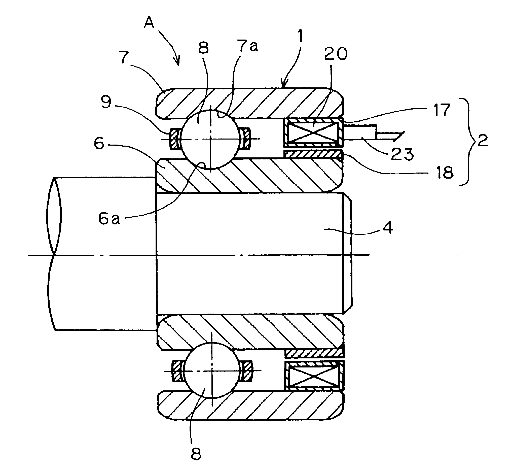
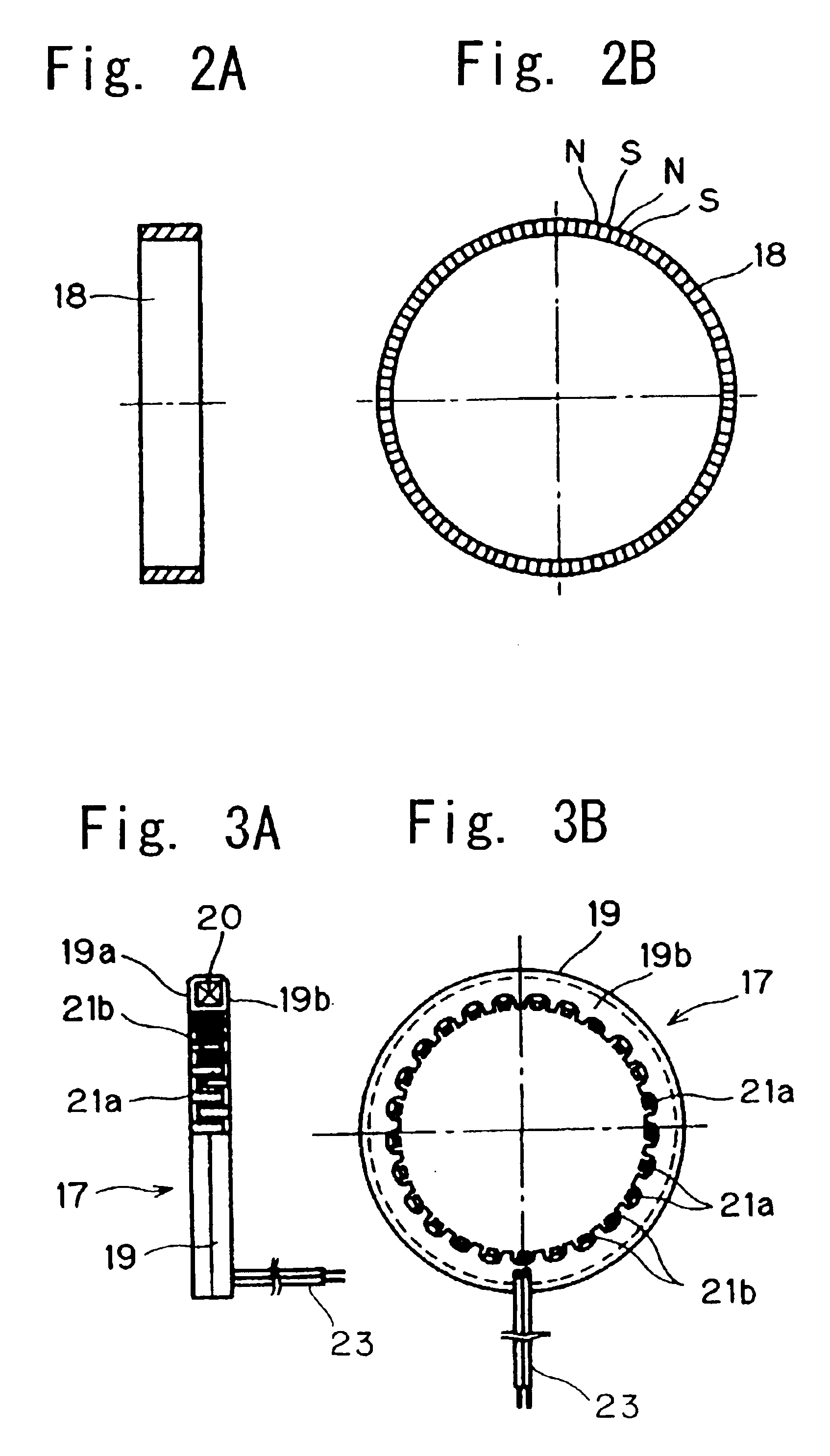
FIG. 6 illustrates a second preferred embodiment of the present invention. The bearing assembly according to this embodiment is similar to that according to the previously described embodiment, except that in place of the claw-pole type, the stator 17 of the electric power generator 2 shown in FIG. 6 is made up of a laminated silicon steel plate 30 with the coil 20 wound therearound. Also, one of the opposite open ends of the annular working space adjacent the electric power generator 2 in the rolling bearing 1 shown in FIG. 6 is covered by a cover 31 that is fitted into the bore of the outer race 7. The lead lines 23 drawn outwardly from the generator stator 17 are drawn out of the rolling bearing 1 through a lead-out hole 31a defined in the cover 31. Other structural features of the bearing assembly shown in FIG. 6 are similar to those shown and described in connection with the first embodiment and, therefore, the details thereof are not reiterated for the sake of brevity.
A third ...
third embodiment
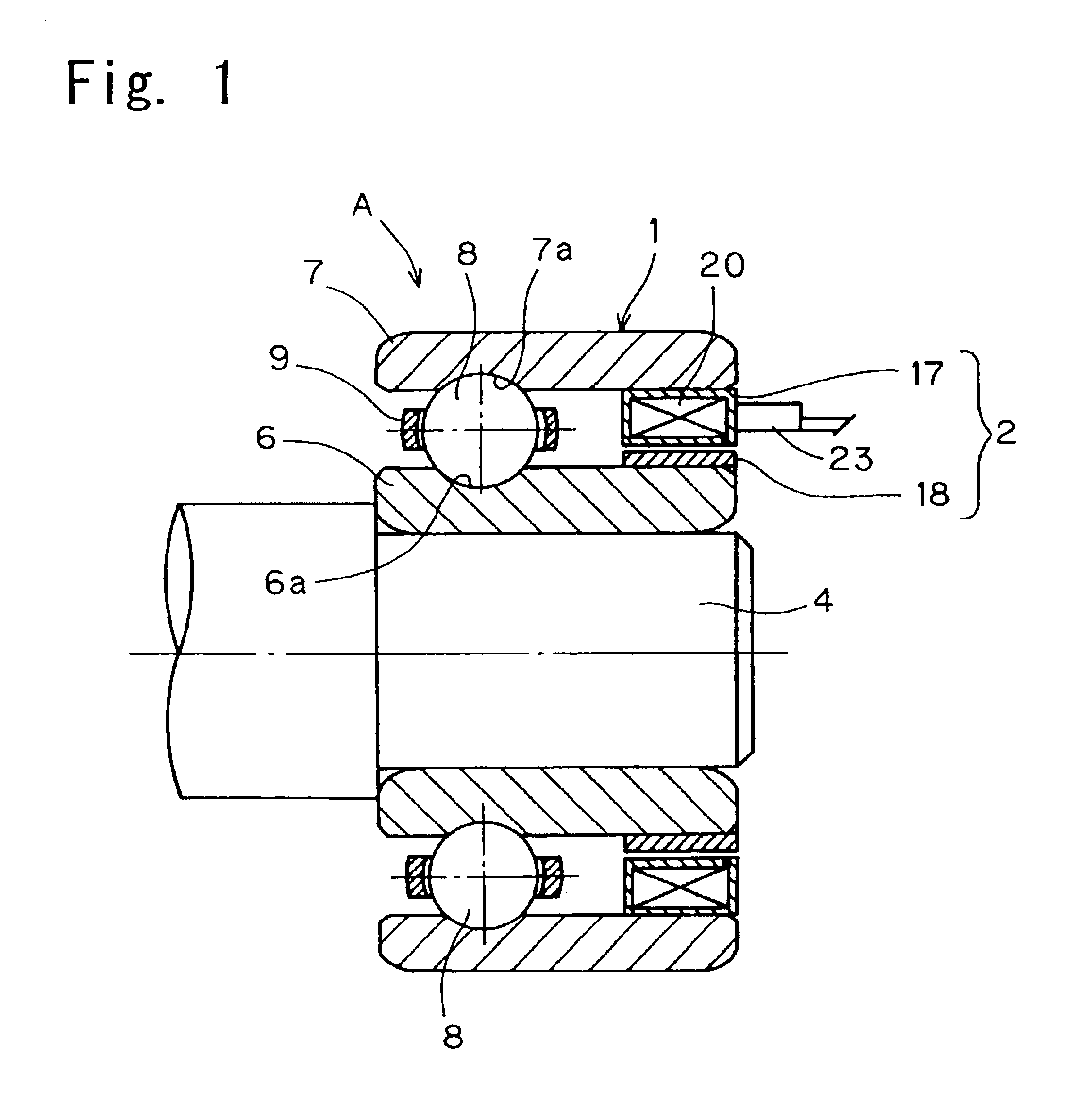
The bearing assembly according to a fourth preferred embodiment of the present invention is shown in FIG. 8. The bearing assembly shown in FIG. 8 is substantially similar to that shown in FIG. 7, except that in the embodiment shown in FIG. 8, as a structural element for fixing the multi-pole magnetized rotor 18 to the inner race 6, a corrugated core metal 18b is employed and mounted on the reduced diameter portion 6b of the inner race 6. The ring-shaped generator rotor 18 employed therein is of a type including a core metal 18b of a metallic plate having a multi-pole magnet member 18a mounted fixedly on an outer periphery of the core metal 18b. The magnet member 18a may be made up of a rubber magnet, a plastic magnet, a sintered alloy or the like. This core metal 18b is of a generally U-sectioned design opening radially outwardly, including opposite end walls and a peripheral wall bridging between the end walls, with the peripheral wall being corrugated in a direction conforming to...
fourth embodiment
FIG. 9 illustrates a modification of the fourth embodiment shown in and described with reference to FIG. 8. Specifically, if the core metal 18b is modified to represent a generally tubular ring encompassing the magnet member 18a substantially in its entirety as shown in FIG. 9, the modified core metal 18b concurrently serves as a covering for the magnet member 18a. Accordingly, even though the magnet member 18a is made of a material, such as a rubber magnet, plastic magnet or the like, susceptible to scratch as a result of collision with foreign matter such as stones or rocks, the modified core metal 18b is advantageously effective to avoid any possible damage to the surface of the magnet member 18a. In this modification, the core metal 18b is preferably made of a non-magnetic material.
It is to be noted that although in the embodiment and its modification shown respectively in FIGS. 8 and 9, the inner race 6 has been shown and described as formed with the reduced diameter portion 6b...
PUM
 Abstract
Description
Claims
Application Information