

Process and apparatus for supplying a gaseous mixture
a gaseous mixture and process technology, applied in mixers, insect catchers and killers, animal husbandry, etc., can solve the problems of pyrophoric, flammability of fumigants and sterilising gases, occupational health and safety problems in handling spent tablets, and potential residue problems
- Summary
- Abstract
- Description
- Claims
- Application Information
AI Technical Summary
Benefits of technology
Problems solved by technology
Method used
Image

Examples
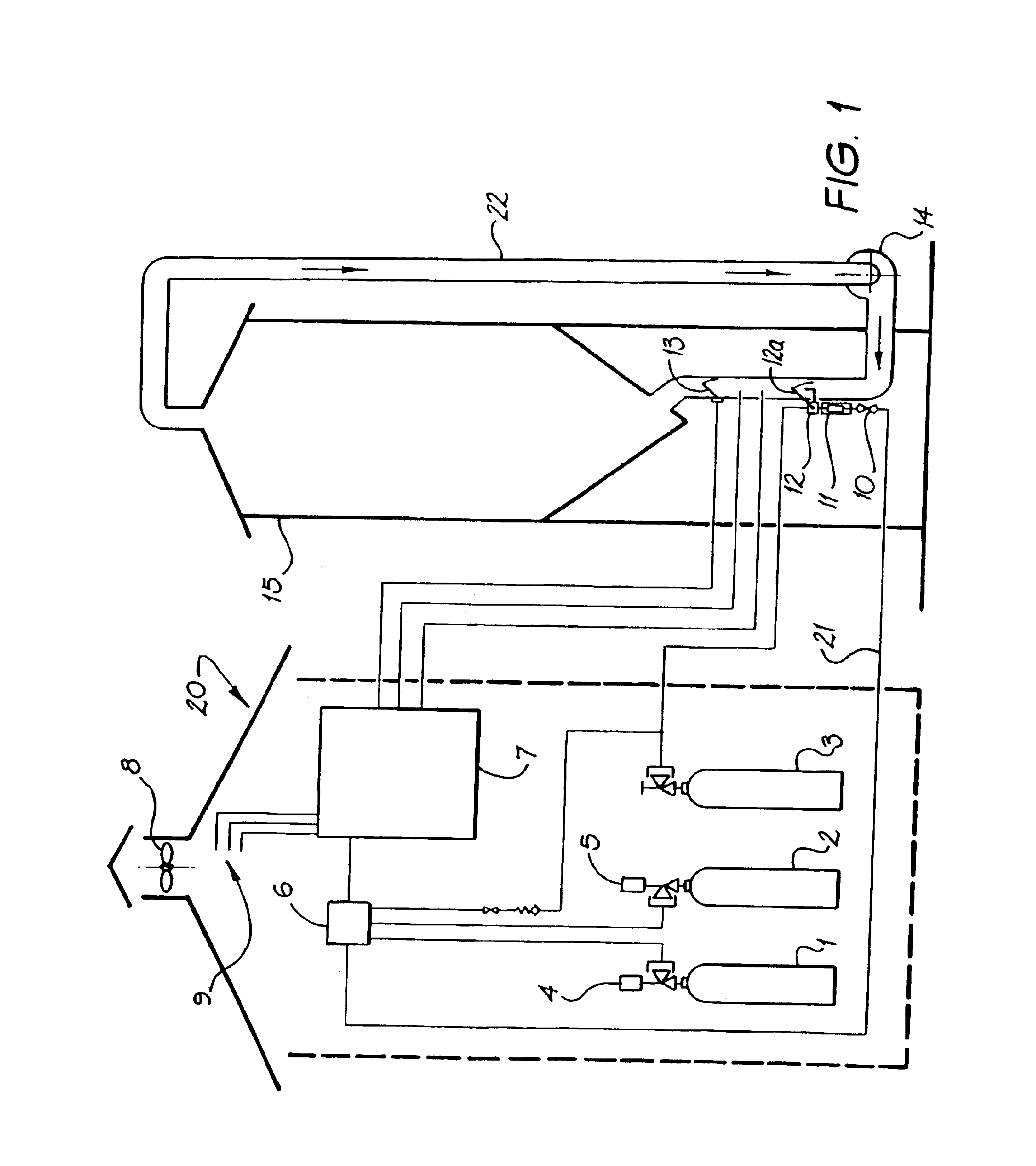
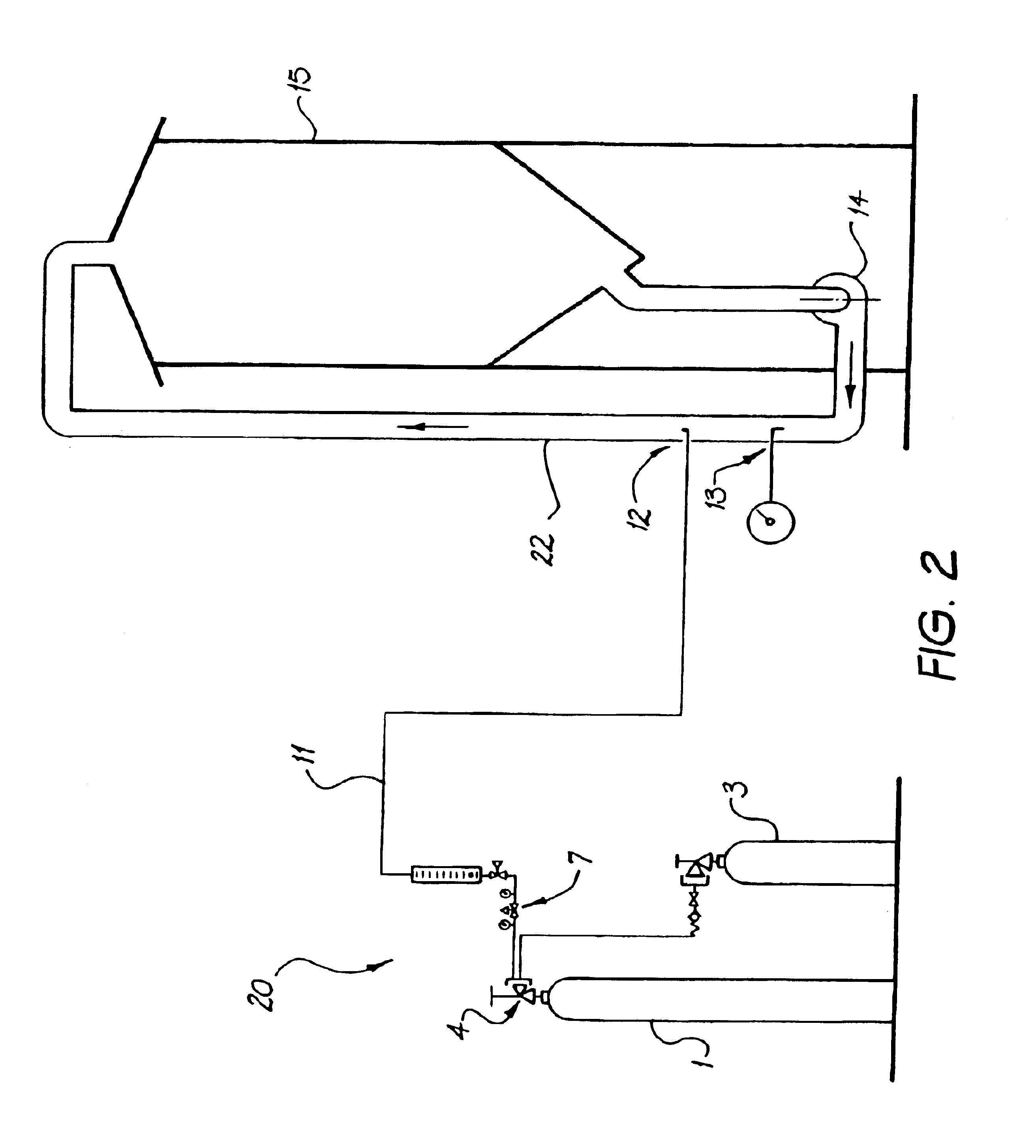
first embodiment
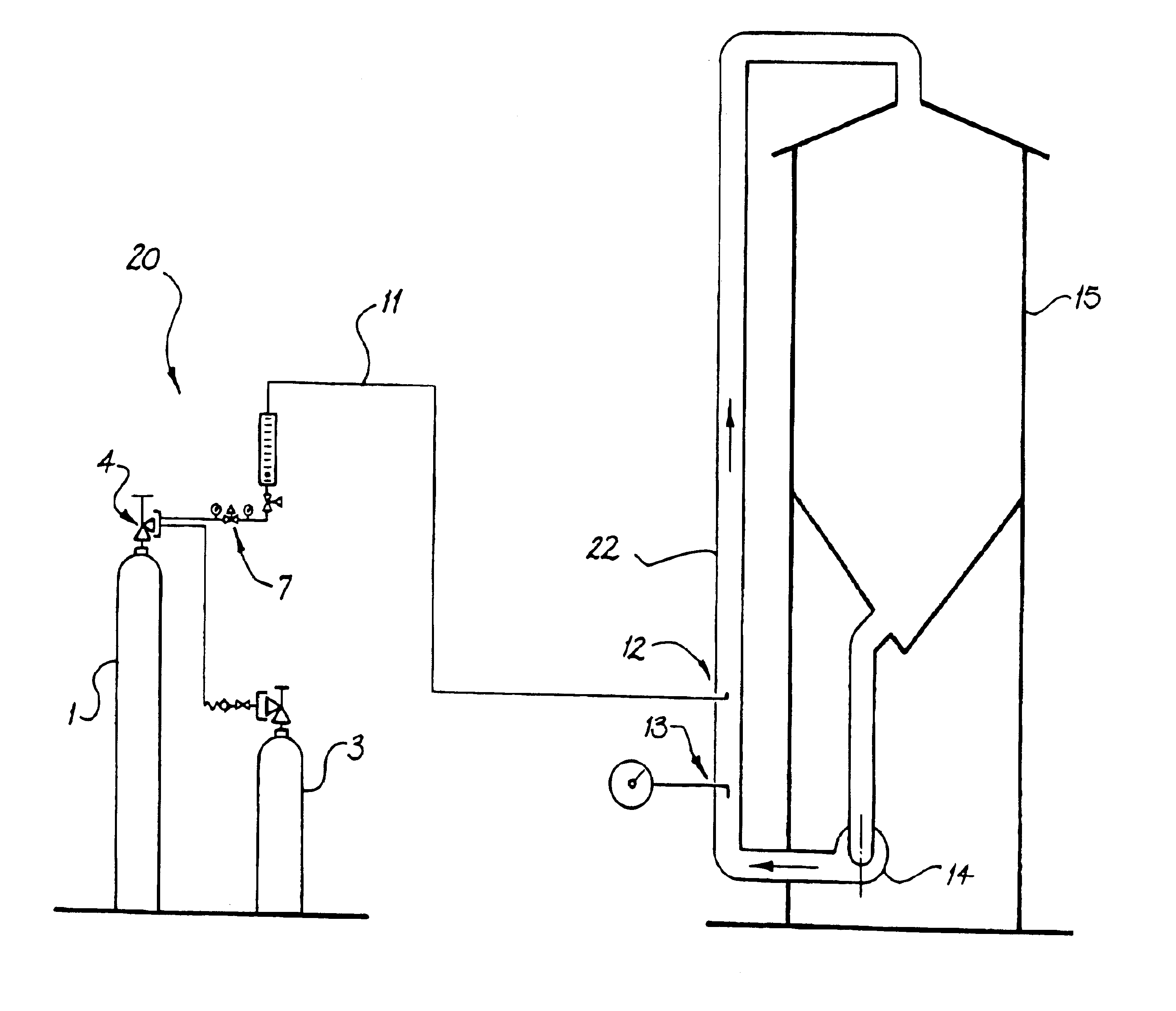
As with the first embodiment, after purging of the supply lines with inert gas, the fumigant gas is injected via line 11 into the turbulent air stream and into silo 15. As mentioned above, this is at a much higher rate than the embodiment of FIG. 1. Concentrations up to 1000 ppm are typical.
In order to dilute such a large quantity of flammable fumigant gas, larger quantities of air are required in the turbulent stream. Volumetric flows up to 103m3 per half hour are typical but of course this will vary with the size of the storage container, conduit etc. With such a ‘one shot’ or ‘quick dump’ fumigation, the silo 15 is normally sealed. The required concentration of gaseous mixture is reached very quickly and, as with the first embodiment, blower 14 may continue to recirculate the resultant gaseous mixture through the silo to ensure thorough treatment, if necessary:
second embodiment
As will be appreciated by persons skilled in the art, the higher concentration and higher flow rates of the gaseous mixture in this second embodiment increase the possibility for ignition / explosion. Due to this fact and given that the treatment process only takes 1 to 2 hours, the ‘one shot / quick dump’ treatment is generally manually operated. In addition to this manual operation, however, other safety devices are used to monitor / isolate the flammable gas supplied in the event of ignition. Typically, various temperature and smoke sensors are used to shut off the flammable gas supply. Thermal fuses can also be used. These fuses comprise pressurised lines made from thermally sensitive material eg plastic. If ignition occurs, the thermally sensitive material degrades thereby releasing pressure in the lines tripping a valve 4 to close the flammable gas supply. In conjunction, the thermal fuse may also open the purge gas lines thereby removing any flammable mixture in the facility.
As wit...
PUM
| Property | Measurement | Unit |
|---|---|---|
| Fraction | aaaaa | aaaaa |
| Speed | aaaaa | aaaaa |
| Flow rate | aaaaa | aaaaa |
Abstract
Description
Claims
Application Information