Gas discharge type display panel and production method therefor

a technology of display panel and gas discharge, which is applied in the manufacture of electric discharge tubes/lamps, electrode systems, gas exhaustion means, etc., can solve the problems of lowering the brightness of lighting the panel, affecting the quality of the panel, and having a small cross-sectional area, etc., to achieve a higher softening point, and a lower softening point

Inactive Publication Date: 2005-01-11
HITACHI LTD
View PDF18 Cites 15 Cited by
  • Summary
  • Abstract
  • Description
  • Claims
  • Application Information

AI Technical Summary

Benefits of technology

As for the seal frit used for bonding the exhaust tube, by making the shape of the exhaust tube so as to allow the area of the bonding surface between the exhaust tube and the substrate to be large enough, there will be no leakage problem in the exhaust operations performed at high temperature even that is using an amorphous glass frit (also including filler materials conditionally) identical to the material used for sealing the substrate. However, when “an amorphous glass frit (also including filler materials conditionally) having higher softening point is used for bonding the exhaust pipe, and an amorphous glass frit (also including filler materials) having lower softening point is used for sealing the substrate”, or “a crystalline glass frit (also including filler materials conditionally) having higher softening point is used for bonding the exhaust pipe, a crystalline glass frit (also including filler materials conditionally) having lower softening point is used for sealing the substrate, and then the exhaust operations are applied after completing the crystallization of the crystalline glass and fixing the exhaust tube”, by making th

Problems solved by technology

However, a small quantity of the gas unusually remaining within the sealing glass after tip off may appear inside of the panel when the panel is discharged.
From the sealing glass, the gas involved at the time of sealing, in addition to the gas associated with the binder, leaks into the inside of the panel while discharging, which may contribute to the lowering of brightness when lighting the panel over an extended time period.
Owing to this, there is a problem in the conventional gas charge type display panels in that the portion having a small cross-sectional area, especially for the cross-sectional area of the sealing glass parallel to the substrates, has a lower strength.
In the process of manufacturing a gas discharge type display panel, a case may accidentally occur in which the gas that is unnecessary for effective discharge remains

Method used


Image

  • Gas discharge type display panel and production method therefor
  • Gas discharge type display panel and production method therefor
  • Gas discharge type display panel and production method therefor

Examples


embodiment 1

(Embodiment 1)

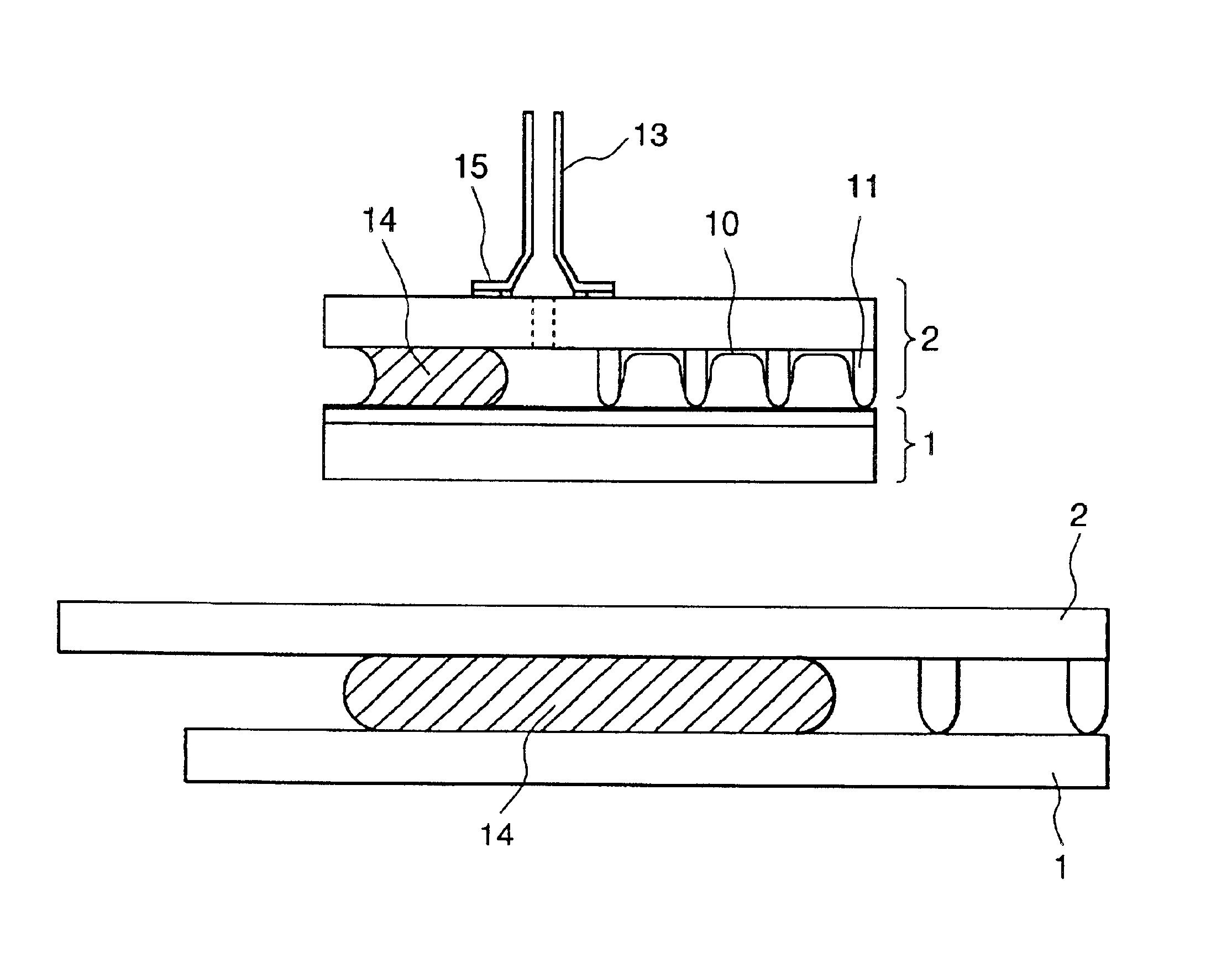
A method of manufacture of plasma display panels representing a first embodiment of the present invention will be described. In this embodiment, a sealing method is used in which the panel is sealed while being subjected to an exhaust operation, and the sealing glass is broken down by using the pressure difference between the inside and outside of the panel. For comparison, a panel manufactured by the conventional sealing method in which the panel is pressurized by clips will be studied as well.

In this embodiment, the pattern for the sealing glass 14 is formed by a dispensing method applied to the back substrate 2, and then, the seal frit is formed by drying and removing the binders. An amorphous glass type seal frit (390° for softening point, 450° for working point and also including the filler materials) is used for the sealing glass 14.

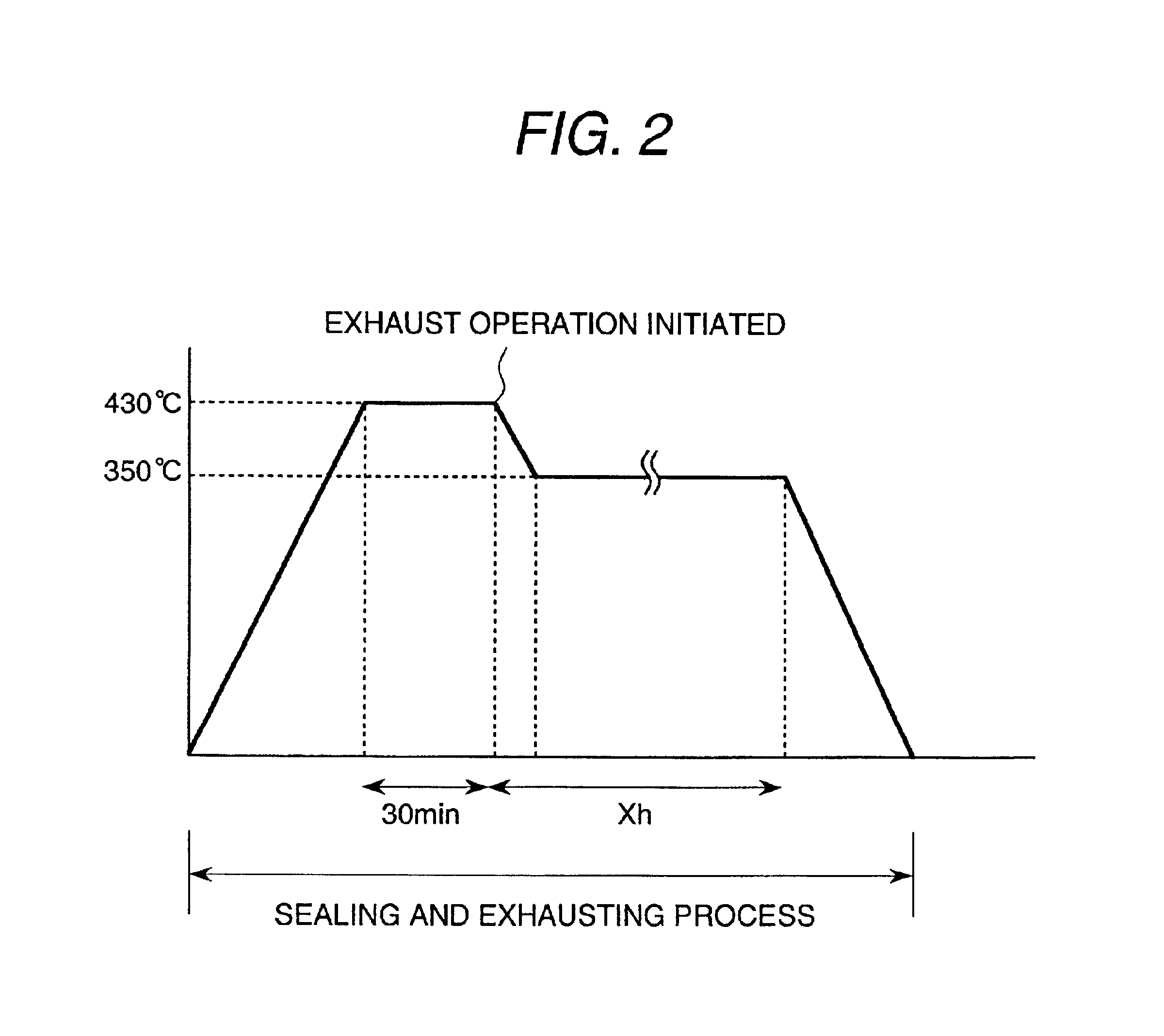
Next, the processes performed after the sealing and exhaust operations will be described. In FIG. 2, a temperature profile for the s...

embodiment 2

(Embodiment 2)

In the second embodiment of the present invention, a plasma display panel is formed by using the different exhaust gas temperature from the first embodiment. FIGS. 8(a) to 8(d) shows the temperature profile for the sealing and exhausting processes.

Another plasma display panel is formed by a procedure which includes initiating the exhausting operation after holding the temperature at 430° C. for 30 minutes and then cooling the panel down to room temperature without maintaining the temperature constant while reducing the temperature. The cross section of the resultant plasma display panel as seen in the direction perpendicular to the back side substrate 2 is then observed. FIG. 9 illustrates diagrammatically the state of the sealing glass 14.

For the panel formed at 450° C. among the panels formed by varying the exhaust gas temperature, the viscosity of the sealing glass 14 is reduced too much and a leakage is formed in the glass for sealing the substrate. In case of seal...

embodiment 3

(Embodiment 3)

In the third embodiment of the present invention, a plasma display panel is manufactured by using a crystalline glass frit (with the softening point at 390° C., the crystallization peak temperature at 430° C. and a filler included) for the sealing glass 14 and an amorphous glass frit (with the softening point at 390° C., the working point at 430° C. and a filler included) for the seal frit bonding between the exhaust pipe 13 and the back substrate 2, and by using an exhaust pipe 13 having a sectional form as shown in FIG. 11(a) or FIG. 11(b). This manufacturing method is the same as that of embodiment 1, and it uses two temperature profiles of the type shown in FIG. 2, including the case (a) in which the first heat reserving process continues for 5 minutes and the second heat reserving process continues for 3.5 hours, and the case (b) in which the first heat reserving process continues for 10 minutes and the second heat reserving process continues for 3.5 hours.

The exh...


PUM


Abstract

In the manufacture of a gas discharge type display panel, by applying a sealing operation along with an exhausting operation, the sealing glass 14 is broken down by a pressure difference between the inside and outside of the panel, and thus, the clearance gap between the substrates can be controlled as desired. In addition, the gaseous component that is unnecessary for the discharge operation is exhausted by setting the temperature of the amorphous sealing glass to exceed its softening-point and be no more than its working point. In the structure of the gas discharge type display panel, a protruding portion having a radius of curvature between 0.1 mm and 1 mm is formed on the sealing glass to reduce the dispersion in the thickness direction of the sealing glass, or the cross-sectional shape of the sealing glass is made convex both at its inside end part and its outside end part.

Description

BACKGROUND OF THE INVENTIONThis invention relates to a gas discharge type display panel, such as a plasma display panel, and a method of manufacture thereof.The production of a gas discharge type display device, especially production processes from seal frit formation to sealing and exhausting, is described in “FPD Intelligence” magazine (June, 1998), pages 84 through 88, for example. The description at page 86 indicates the necessity of selecting an exhaust temperature not exceeding the softening point of the sealing glass.Also, in a method of manufacture of a gas discharge type display panel, such as a plasma display panel, it is necessary to exhaust the inside of the panel in advance of the inclusion of a discharge gas. To do this, in addition to the above-mentioned method of exhausting only the inside of the panel after the sealing, a method of exhausting the whole of a furnace during the sealing so as to exhaust both the inside and outside of the panel at one time is also known...

Claims


Application Information

Patent Timeline
IPC IPC(8): H01J9/26H01J11/34H01J11/38H01J11/46H01J11/48H01J11/54H01J17/18
CPCH01J9/261H01J2217/49264H01J2217/49H01J9/26H01J11/34H01J11/38
Inventor MOTOWAKI, SHIGEHISAMURASE, TOMOHIKOKAWAI, MICHIFUMISATO, RYOHEIMATSUOKA, YASUHIROKATO, YOSHIHIRONAITO, TAKASHISUZUKI, YASUTAKA
Owner HITACHI LTD
Why Eureka
Try Eureka