Method for operating a fuel cell plant and fuel cell plant

Inactive Publication Date: 2005-01-11
SIEMENS AG
View PDF16 Cites 1 Cited by
  • Summary
  • Abstract
  • Description
  • Claims
  • Application Information

AI Technical Summary

Benefits of technology

In an expedient configuration of the invention, the housing is thermally insulated. This substantially prevents the hot air in the housing from heating the outer wall of the housing and the housing itself from radiating heat into the environment.
The housin

Problems solved by technology

However, this measur

Method used


Image

  • Method for operating a fuel cell plant and fuel cell plant
  • Method for operating a fuel cell plant and fuel cell plant

Examples


Embodiment Construction

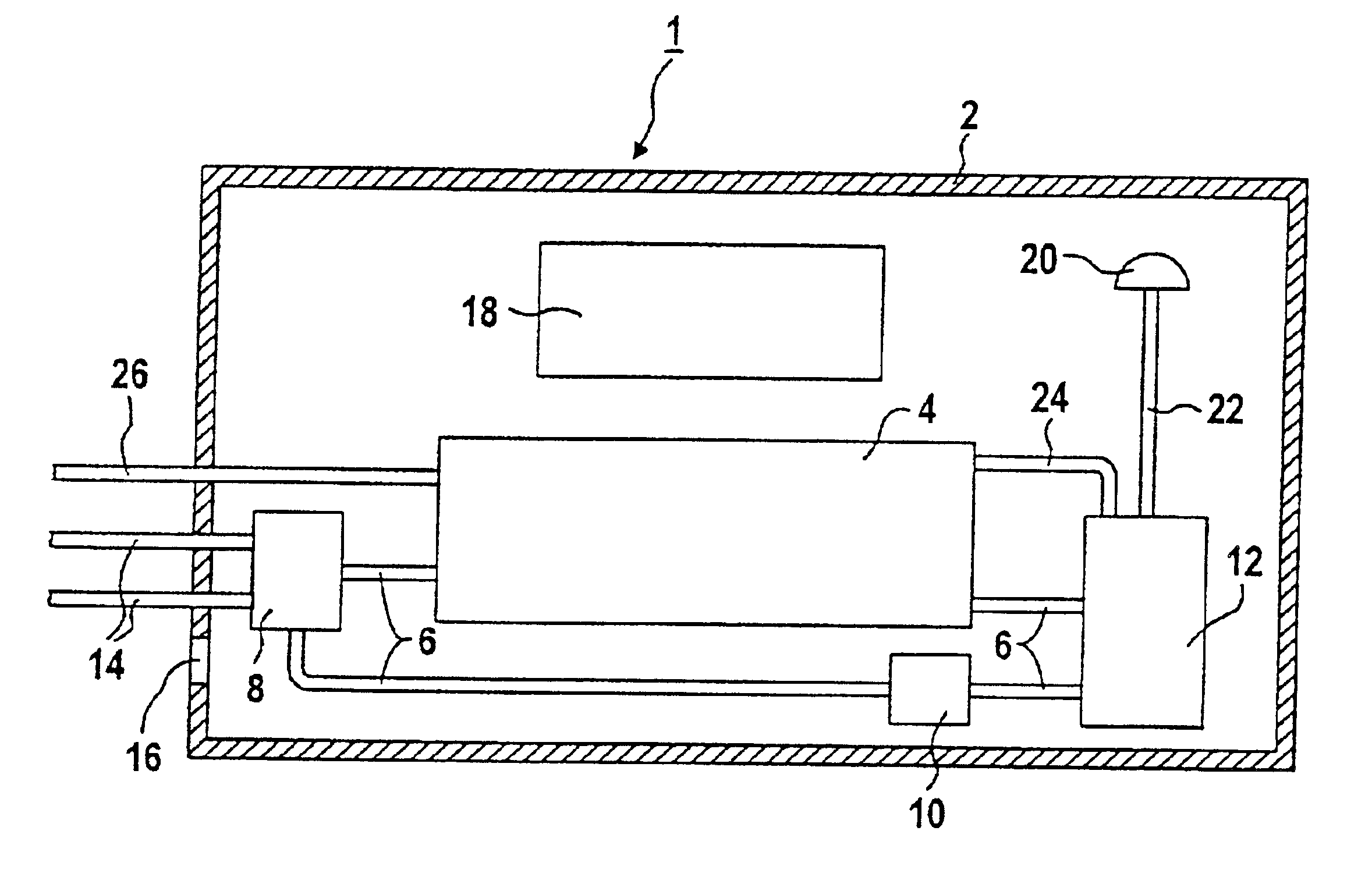
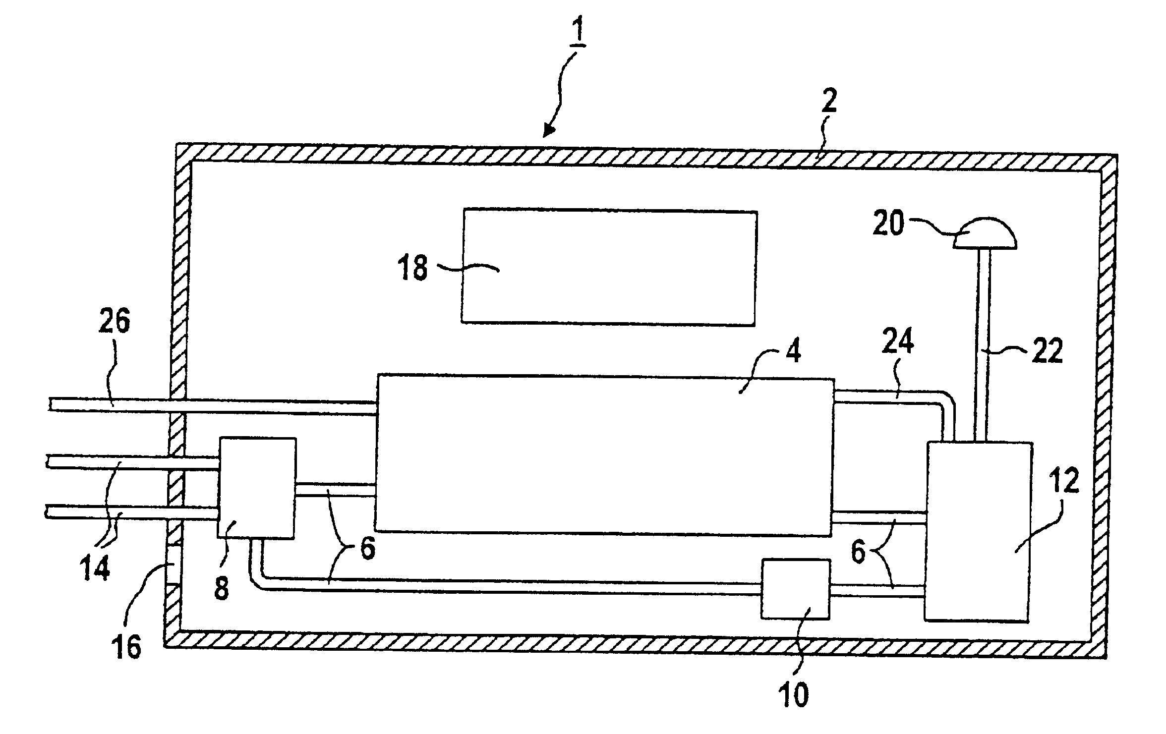
Referring now in detail to the single FIGURE of the drawing, there is seen a very greatly simplified illustration of a fuel cell plant 1. A thermally insulated housing 2 surrounds all other components of the fuel cell plant 1. A fuel cell block 4, which includes 80 PEM fuel cells, is disposed in the housing 2. The fuel cell block 4 is cooled by water in a cooling circuit 6, which flows from the fuel cell block 4 to a heat exchanger 8, from there to a circulation pump 10, then onward to a liquid ring compressor 12 and back into the fuel cell block 4. In the heat exchanger 8, the cooling water emits heat to water in a heating-water circuit 14. The water of the heating-water circuit 14 heats household heating systems.

The PEM fuel cells are operated by using air and hydrogen as operating gases. Air from the environment of the fuel cell plant 1, which is at a temperature of approximately 20° C., is passed through an opening 16 in the housing 2 into the interior of the housing 2, as a res...


PUM


Abstract

A method for operating a fuel cell plant and a fuel cell plant are provided. The thermal efficiency of a fuel cell plant results from the useful heat which is generated per quantity of fuel. Heat which is radiated from the fuel cell plant into the environment is lost and cannot be utilized. The method minimizes the radiation of heat from the fuel cell plant. Air for operation of the fuel cells is passed into a housing which surrounds heat-radiating components of the fuel cell plant. The air flows around the components, absorbs the heat which is radiated and delivers it to the fuel cell block, where the heat is emitted to cooling water that cools the fuel cell block and transfers the heat to water of a heating-water circuit.

Description

BACKGROUND OF THE INVENTIONField of the InventionThe invention relates to a method for operating a fuel cell plant and to a fuel cell plant.It is known that during the electrolysis of water, water molecules are broken down into hydrogen (H2) and oxygen (O2) by electric current. In a fuel cell, that operation takes place in the reverse direction. Electrochemical combining of hydrogen and oxygen to form water results in electric current being generated with a high efficiency, and without any emission of pollutants and carbon dioxide (CO2) if pure hydrogen is used as the fuel gas. Even with a technical-grade fuel gas, for example natural gas or coal gas, and with air instead of pure oxygen, in which case the air may additionally be enriched with oxygen, a fuel cell produces significantly fewer pollutants and less carbon dioxide than other energy generators which operate with fossil energy carriers.The technical implementation of the fuel cell principle has led to various solutions, spe...

Claims


Application Information

Patent Timeline
IPC IPC(8): H01M8/04H01M8/24F24J3/00H01M8/02H01M8/04007H01M8/04014H01M8/247
CPCF24J3/00H01M8/04007Y02E60/50H01M8/247H01M2300/0082H01M8/04014F24V99/00
Inventor BETTE, WILLIMERKEL, CHRISTIAN
Owner SIEMENS AG
Why Eureka
Try Eureka