System and method for equalizing transmission characteristics in wavelength division multiplexing optical communication system

a transmission characteristic and wavelength division multiplexing technology, applied in multiplex communication, transmission monitoring, instruments, etc., can solve the problems of difficult evaluation of the reliability of optical communication systems based on optical amplification using edfas, affecting succeeding stages, and unable to remove the noise produced at each stage, so as to reduce the burden of pre-emphasis control and improve transmission quality.

Inactive Publication Date: 2005-01-25
FUJITSU LTD
View PDF15 Cites 23 Cited by
  • Summary
  • Abstract
  • Description
  • Claims
  • Application Information

AI Technical Summary

Benefits of technology

It is therefore an object of the present invention to provide a transmission characteristic equalizing system and method for use in WDM optical communication systems which, while alleviating the burden on pre-emphasis control, permit the transmission characteristics for all channels to be equalized and optimized effectively and for a better transmission quality to be realized.

Problems solved by technology

On the other hand, since no retiming operation is involved, the noise produced at each stage cannot be removed, which affects succeeding stages.
For this reason, it is difficult to evaluate the reliability of optical communication systems based on optical amplification using EDFAs.
There is a slight increase in noise in each of the optical fiber amplifiers.
Merely measuring the BER (Bit Error Rate), as was done before, is not sufficient to determine the degree of the effect.
In real systems, however, degradation of the transmission characteristics varies from channel to channel.
However, the amounts of pre-emphasis have an upper limiting value (the difference between the maximum optical signal power and the minimum optical signal power allowed for pre-emphasis).
When the upper limiting value is exceeded, there arises the possibility of degradation in the transmission characteristics due to a non-linear effect and degradation in OSNR in the terminal station.
Particularly, as in submarine optical fiber communication systems, and in systems expected to experience increases in transmission distance and speed in the future, it is anticipated that limitations in the amounts of pre-emphasis and design criteria of repeaters will become increasingly strict and mere conventional pre-emphasis based transmission characteristic equalization control will not be able to achieve the performance required of the systems
However, the gain cannot be equalized perfectly due to manufacturing errors of EDF and LPG.
However, such variable control has heretofore not been performed; instead, a selection is made from a plurality of previously prepared optical filters, each with a fixed transmission factor versus wavelength characteristic.
With such a system, however, it is not impossible to equalize the gain with flexibility.

Method used


Image

  • System and method for equalizing transmission characteristics in wavelength division multiplexing optical communication system
  • System and method for equalizing transmission characteristics in wavelength division multiplexing optical communication system
  • System and method for equalizing transmission characteristics in wavelength division multiplexing optical communication system

Examples


first embodiment

[First Embodiment]

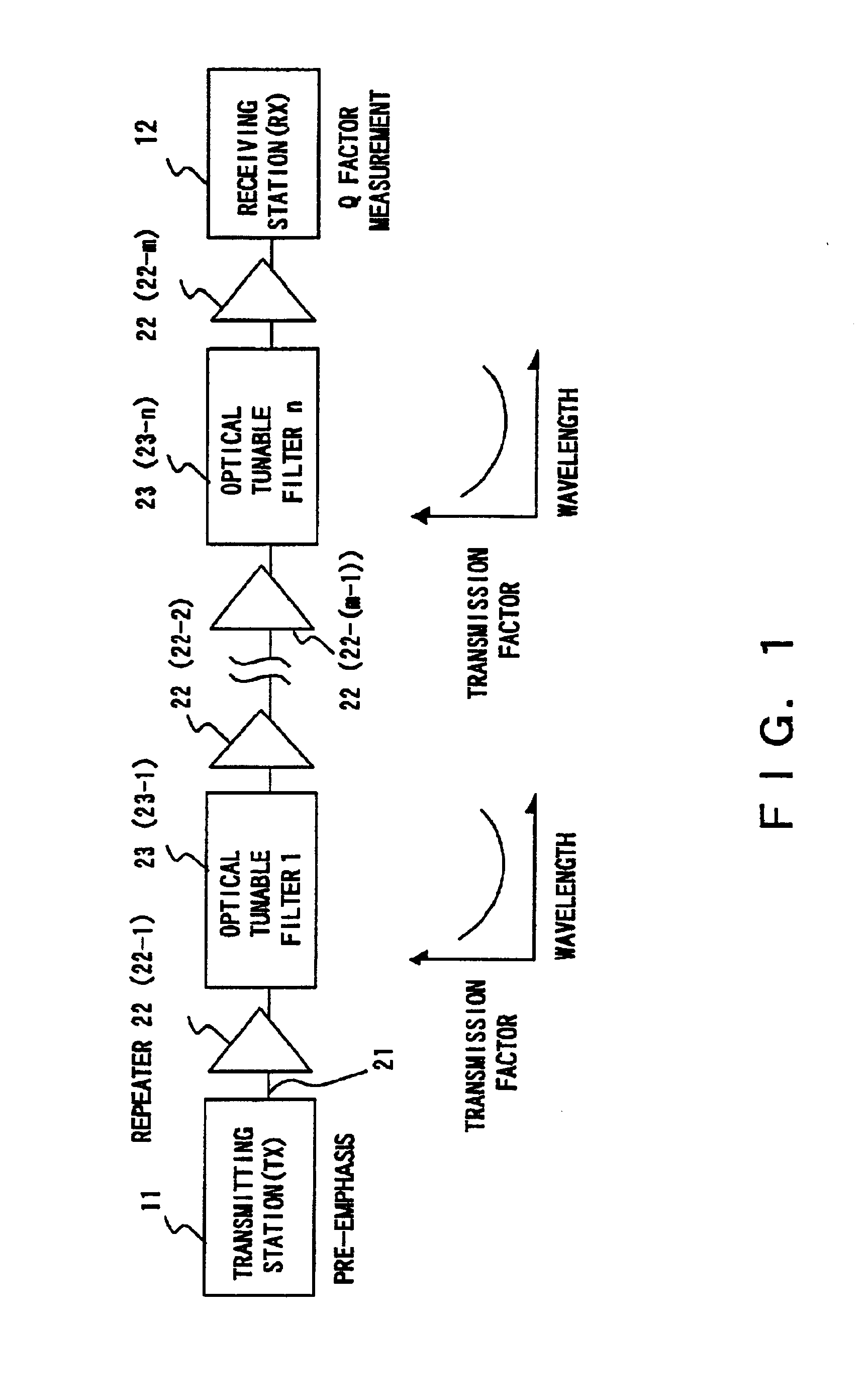
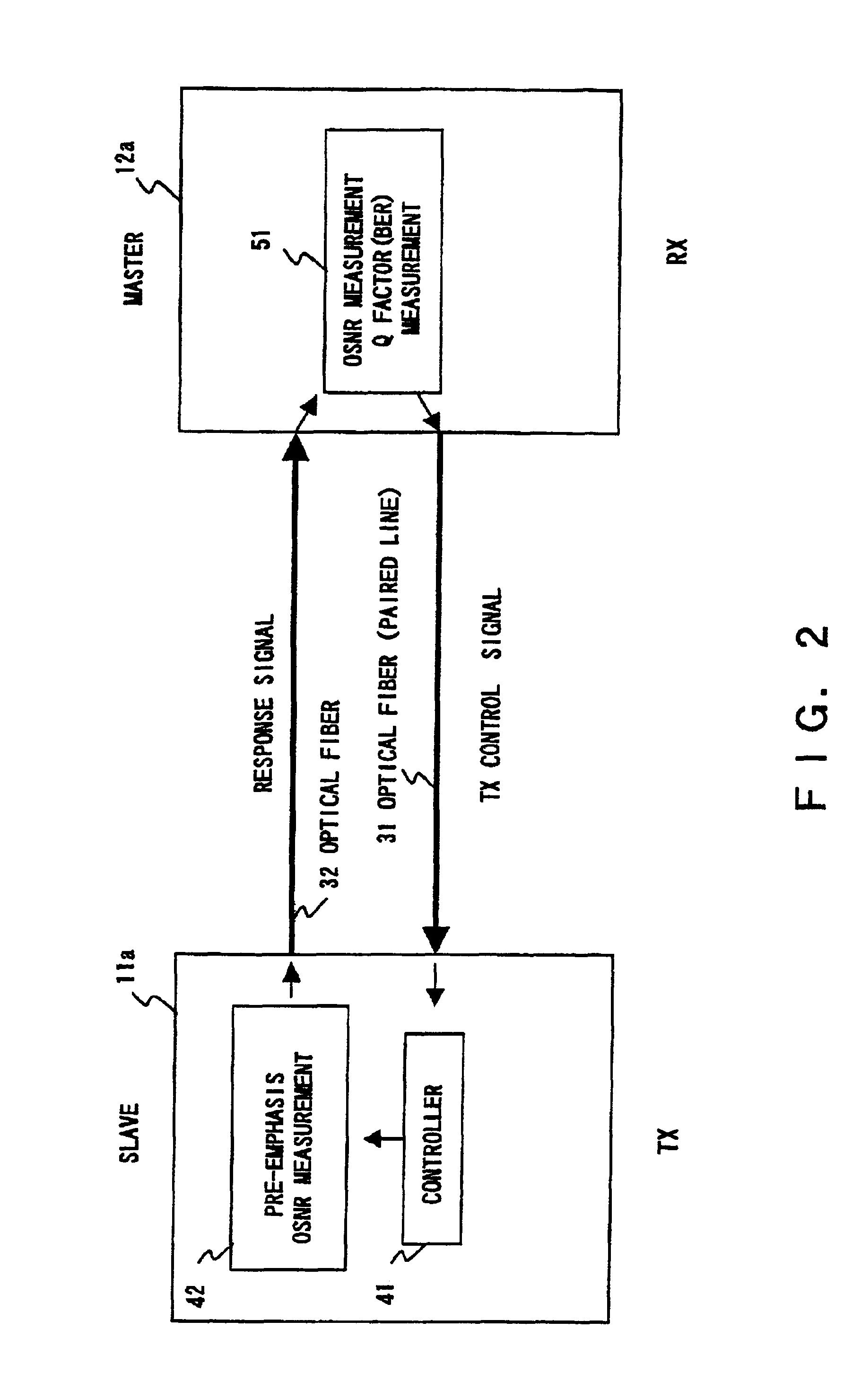
FIGS. 2 and 3 are schematic conceptual diagrams for use in explaining the overall operation of a first embodiment of the invention applied to the system of FIG. 1. More specifically, FIG. 2 is a diagram for use in explaining the operation of a receiving station 12a to control the pre-emphasis in a transmitting station 11a and FIG. 3 is a diagram for use in explaining the operation of the receiving station 12a to control the optical tunable filters 23 via the transmitting station 11. In the first embodiment, the receiving station 12a serves as the master station, while the transmitting station 11a serves as the slave station. Note that the optical filters 23 are omitted in FIG. 2. Each of the control operations will be described briefly below.

(A) Control of the pre-emphasis in the transmitting station (FIG. 2)

The receiving station 12a has a measurement section 51 that functions as a transmission characteristic measurement unit and a transmission characteristic contr...

second embodiment

[Second Embodiment]

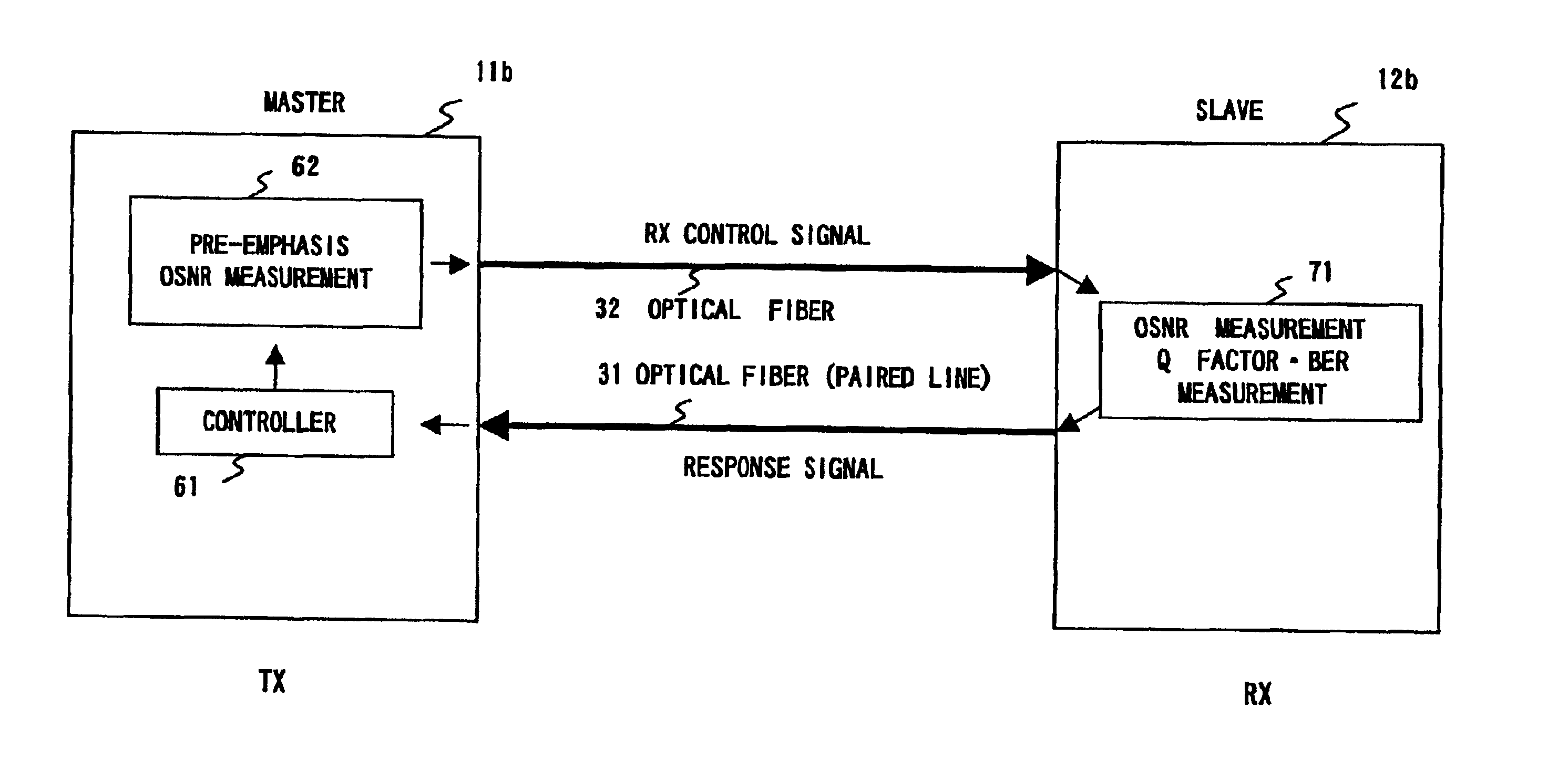
FIGS. 14 and 15 are schematic diagrams for use in explaining the overall operation of a second embodiment of the present invention which is applied to the system of FIG. 1. More specifically, FIG. 14 is a diagram for use in explaining the operation of a transmitting station 11b to control a receiving station 12b and FIG. 15 is a diagram for use in explaining the operation of the transmitting station 11b to control an optical tunable filter 23. In FIG. 14, the optical tunable filter 23 is omitted. Hereinafter, each control operation will be described briefly.

(A) Pre-emphasis control in the transmitting station (FIG. 14)

The transmitting station 11b has a controller 61 and a pre-emphasis controller 62 serving as a transmission characteristic control unit and sends instructions to the receiving station 12b over an optical fiber 32 to measure OSNRs and Q factors and to send back the measurements.

The receiving station 12a has a measurement section 71 as a transmission c...

third embodiment

The third embodiment and the first embodiment differ from each other only in that the first Q equalization is made only through the filter control or the pre-emphasis control. A detailed description of the third embodiment is omitted herein. Such a third embodiment will also provide the same advantages as the first embodiment.

Of course, the second embodiment may also be modified such that the Q factor equalization is first performed through only the pre-emphasis control and then the Q factor equalization and optimization are performed through both the filter control and the pre-emphasis control with reference to the amounts of pre-emphasis at the time of the first pre-emphasis control.

[Other Embodiments]

(1) In the above embodiments, as the control signal transmission method, the control signal is transmitted in the overhead as shown in FIG. 7A; however, this is not restrictive. In the present invention, basically the control signal may be transmitted in any form. The preferred trans...


PUM


Abstract

In a WDM optical communication system, at least one optical tunable filter is placed along an optical fiber provided as an optical transmission path between a transmitting station and a receiving station. The optical tunable filter has a controllable transmission factor versus wavelength characteristic. In the receiving station, the transmission characteristics (for example, optical signal to noise ratios and Q factors) for optical signals of different wavelengths propagated over the optical fiber are measured. The measurements are sent to the transmitting station. The transmitting station then properly controls both the amounts of pre-emphasis in the transmitting station and the wavelength characteristic of the optical filter on the basis of the measurements to thereby equalize the transmission characteristics for the optical signals. In this case, it is also possible to calculate the optimum proportion of allocation of control between the pre-emphasis control and the filter control and then perform the pre-emphasis control and the filter control according to the optimum proportion of allocation. In this control, the main controller may be either the transmitting station or the receiving station.

Description

BACKGROUND OF THE INVENTION1. Field of the InventionThe present invention relates to a system and method for equalizing and optimizing the transmission characteristics in wavelength division multiplexing optical communication systems.2. Description of the Related ArtMany business companies are now beginning to adopt wavelength division multiplexing (WDM) as the core technology for high-speed networks. Wave division multiplexing is a technique which combines a plurality of carrier waves of different wavelengths, each modulated with a data signal, for simultaneous transmission over a single-core optical fiber cable and utilizes the property that optical beams of different wavelengths do not interfere with one another.In optical communication systems using such WDM technology, the transmission characteristics are observed in terms of optical signal to noise ratios (OSNR: optical SN ratio) and Q factors.Here, we explain the background of the introduction of the Q factors as a new evalua...

Claims


Application Information

Patent Timeline
Patent Type & Authority Patents(United States)
IPC IPC(8): H04B10/17H04J14/02H04B10/07H04B10/2507H04B10/2543H04B10/294H04J14/00
CPCH04B10/2941H04J14/025H04J14/0279H04J14/0246H04J14/0221H04J14/0226
Inventor NAKAJIMA, ISAOHARASAWA, SHIN-ICHIROU
Owner FUJITSU LTD
Why Eureka
Try Eureka