MR imaging method and medical device for use in method

a magnetic resonance and imaging method technology, applied in the field of magnetic resonance imaging methods, can solve the problems of inability to achieve, inability to achieve, and inability to amplify the magnetic alternating field

Inactive Publication Date: 2005-01-25
AMRIS PATENTE VERW
View PDF25 Cites 249 Cited by
  • Summary
  • Abstract
  • Description
  • Claims
  • Application Information

AI Technical Summary

Benefits of technology

[0017]The object of the present invention is to provide an MR imaging method for representing and determining the position of an unfoldable medical device, defined herein as a medical device that at least in part

Problems solved by technology

This results in amplification of the magnetic alternating field within the inductance of the resonance circuit.
Even with identical relaxation times and with an identical spin density, the signal from the compartment surrounding the resonance circuit is clearly more intensive than the signal of the other parts of the image.
Often this is not possible.
However, ferromagnetic or paramagnetic metals or impurities in other materials result in artifacts in the images.
Problems result from the tools used for interventional and minimally invasive techniques since they usually consist of ferromagnetic or p

Method used


Image

  • MR imaging method and medical device for use in method
  • MR imaging method and medical device for use in method
  • MR imaging method and medical device for use in method

Examples


Embodiment Construction

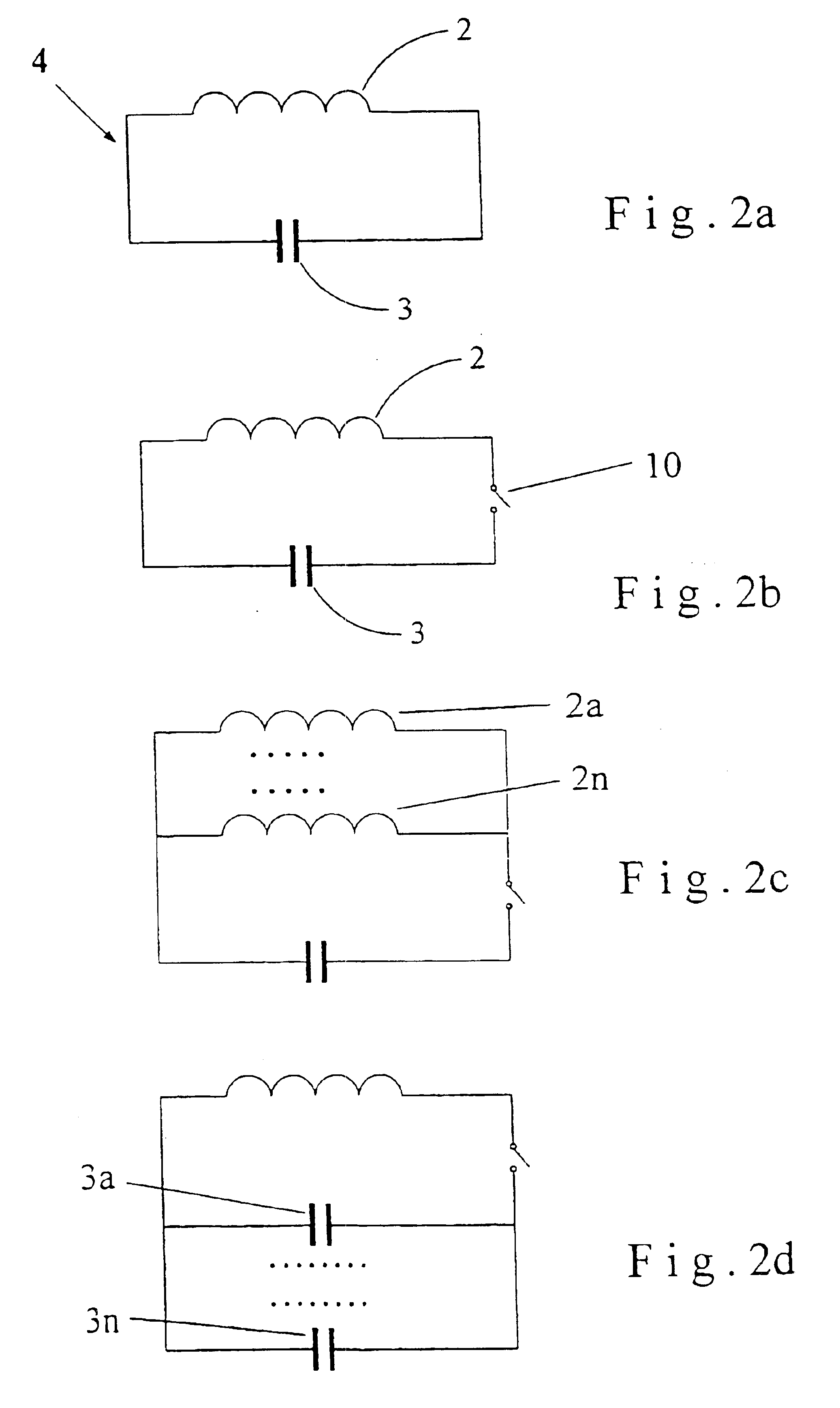
">[0040]FIGS. 2a-2g—various electrical diagrams of a resonance circuit according to the invention;

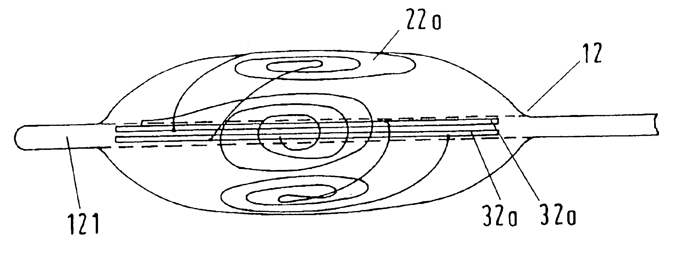
[0041]FIGS. 3a and 3b—two exemplary embodiments of a balloon catheter designed according to the invention;

[0042]FIG. 4—a medical instrument with resonance circuits mounted on the sides of the instrument;

[0043]FIG. 5—a perspective depiction of an alternative embodiment of the medical instrument of FIG. 4;

[0044]FIGS. 6a and 6b—two exemplary embodiments of a dental implant designed according to the invention;

[0045]FIGS. 7a and 7b—two exemplary embodiments of a joint implant designed according to the invention;

[0046]FIGS. 8a and 8b—two exemplary embodiments of a vena cava filter designed according to the invention; and

[0047]FIGS. 9a and 9b—two exemplary embodiments of a cardiac valve designed according to the invention.

DETAILED DESCRIPTION OF THE INVENTION

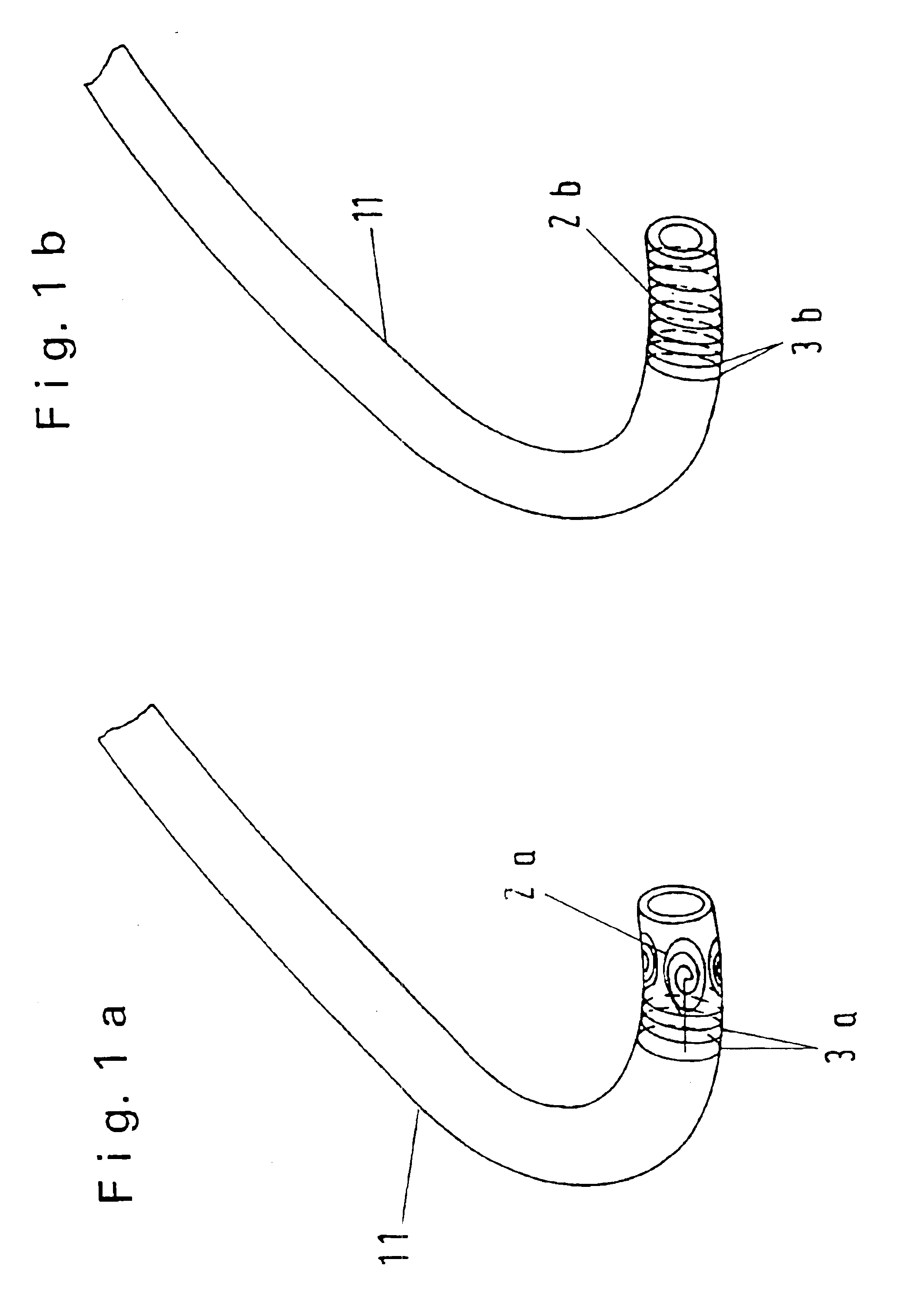
[0048]FIGS. 1a and 1b depict a guide wire or catheter 11, on the point of which a resonance circuit consisting of an inductor 2a, 2b and ...


PUM


Abstract

The invention relates to an MR imaging method for representing and determining the position of a medical device inserted in an examination object, and to a medical device used in the method. In accordance with the invention, the device (11) comprises at least one passive oscillating circuit with an inductor (2a, 2b) and a capacitor (3a, 3b). The resonance frequency of this circuit substantially corresponds to the resonance frequency of the injected high-frequency radiation from the MR system. In this way, in a locally limited area situated inside or around the device, a modified signal answer is generated which is represented with spatial resolution.

Description

FIELD OF THE INVENTION[0002]The invention relates to an MR (magnetic resonance) imaging method for representing and determining the position of a medical device inserted in an examination object according to the generic part of claim 1 and a medical device for use in the method.BACKGROUND OF THE INVENTION[0003]MR imaging methods have been known for some time. They are based on the resonance alternating effect between a high-frequency (HF) electromagnetic alternating field and specific atomic nuclei of an object to be examined, in particular a human or an animal body that is arranged in a strong external magnetic field. The atomic nuclei precess in the magnetic field (B0) by the so-called Lamor frequency that is proportional to the strength of the magnetic field. When applying an electromagnetic alternating field whose magnetic alternating component (B1) is perpendicular to the direction of the strong magnetic field (B0), the spins of the atomic nuclei flip and associated relaxation ...

Claims


Application Information

Patent Timeline
IPC IPC(8): A61F2/06A61B5/055A61B5/06G01R33/28A61F2/00G01R33/34A61F2/86
CPCA61B5/055A61B5/411A61F2/86G01R33/285G01R33/286G01R33/34053G01R33/34084A61B5/06A61F2230/0091A61B5/4547A61F2250/0045A61F2220/005A61F2220/0058A61F2230/0021A61F2230/0058A61F2230/0086
Inventor MELZER, ANDREASBUSCH, MARTIN
Owner AMRIS PATENTE VERW
Why Eureka
Try Eureka