
Electric power steering apparatus

a technology of electric power steering and electric motor, which is applied in mechanical devices, transportation and packaging, and packaging, etc., can solve the problems of increasing costs, achieve the effects of improving the assembling efficiency of the motor, improving the tough or feeling of steering, and reducing the vibration of the rack sha

Inactive Publication Date: 2005-02-01
HONDA MOTOR CO LTD
View PDF11 Cites 19 Cited by
  • Summary
  • Abstract
  • Description
  • Claims
  • Application Information

AI Technical Summary

Benefits of technology

[0018]It is accordingly an object of the present invention to provide an electric power steering apparatus having structural features which enable substantial reduction of assembling and inspection man-hours and cost.
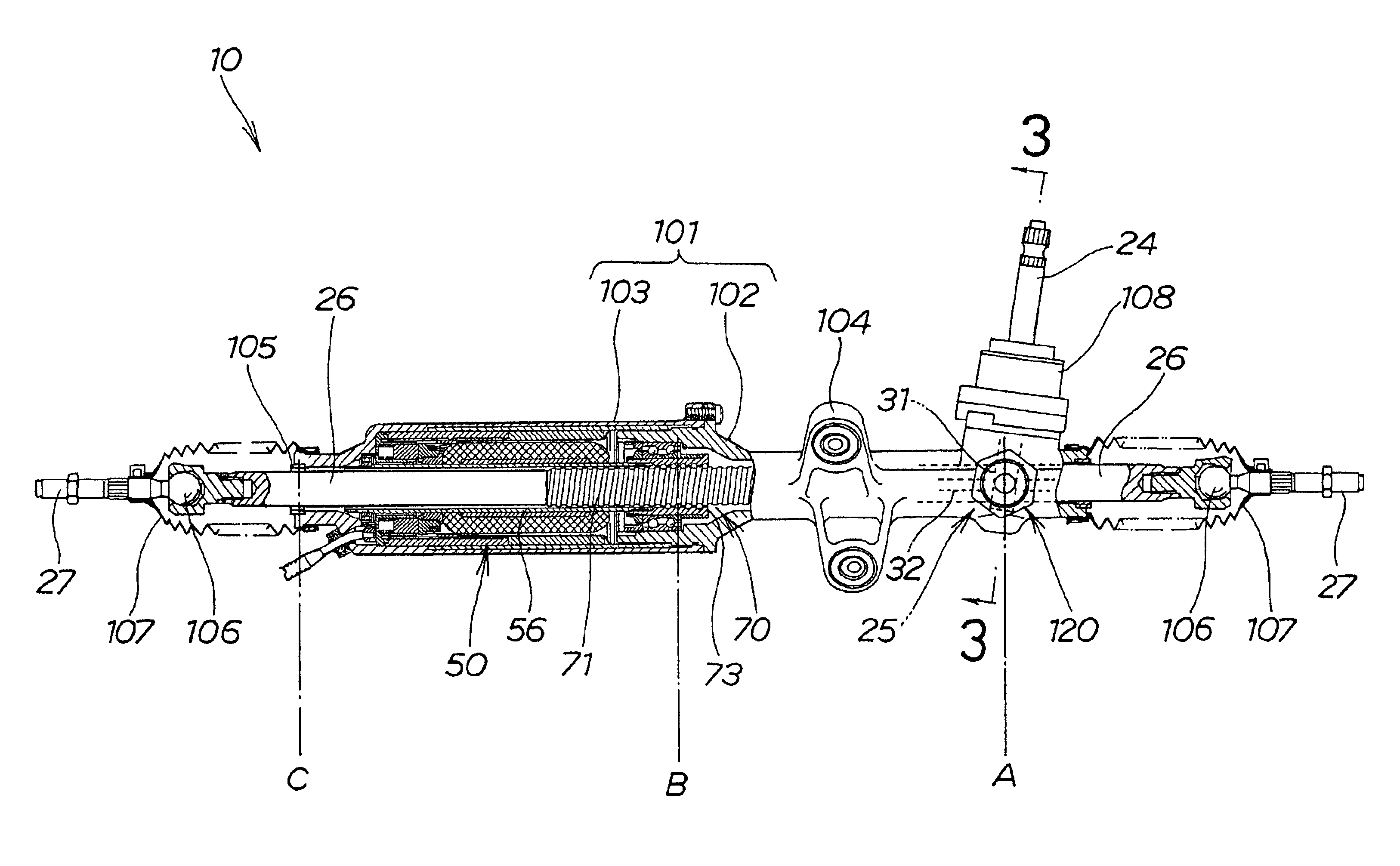
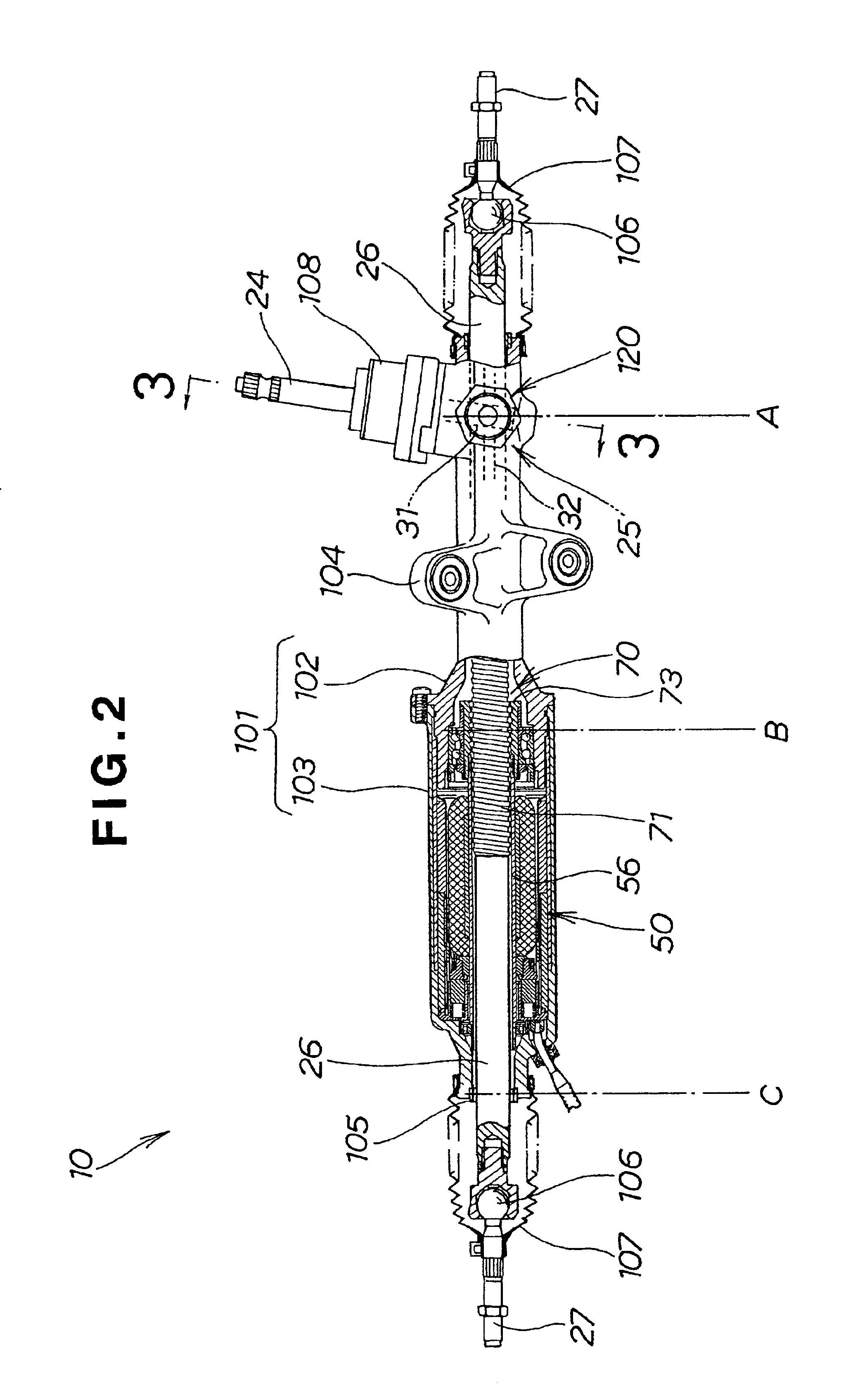
[0020]The nut of the ball-screw mechanism is assembled in the electric power steering apparatus before the motor shaft is connected to the nut. This arrangement ensures that after the electric motor is subjected to a quality inspection and performance test, the rack shaft and the ball-screw mechanism can be assembled with the electric motor while keeping the motor in an assembled state. This eliminates a disassembling process due in the conventional electric power steering apparatus before the electric motor is assemble with the rack shaft and the ball-screw mechanism and a quality inspection and performance test due also in the conventional electric steering apparatus after the electric motor is assemble with the rack shaft and the ball-screw mechanism. The electric power steering apparatus of the present invention is, therefore, assembled easily and efficiently and can be manufactured at a relatively low cost. Furthermore, the electric motor is not subjected to a reassembly process and hence can retain a high assembling accuracy.
[0021]It is preferably that the motor shaft and the nut are fitted together in the longitudinal direction of the rack shaft so as to form a connection capable of transmitting a torque between the motor shaft and the nut. Since the connection can be formed by merely fitting together the motor shaft and the nut in the longitudinal direction of the rack shaft, the man-hours due for assembling the motor shaft and the nut can be reduced.
[0022]Preferably, the connection includes a torque limiter acting between the motor shaft and the nut to release the engagement between the motor shaft and the nut when subjected to a torque larger than a predetermined value. The electric motor is thus protected against damage when subjected to an undue force or load.
[0024]The electric motor includes a commutator attached to the motor shaft and having a brush-contact surface, and brushes being in slide contact with the brush-contact surface of the commutator, the brush-contact surface extending in a plane perpendicular to the axis of the motor shaft. The brushes abut on the brush-contact surface in the axial direction of the motor shaft. This arrangement allows the brushes and commutator to be assembled together from a direction same as the direction of assembly of the motor shaft, which leads to a further improvement in the assembling efficiency of the motor.
[0025]The electric power steering apparatus may further comprise a rack guide disposed on a back side surface of the peripheral surface of the rack shaft, diametrically opposed from the peripheral surface portion on which the rack is formed, for pressing the back side surface toward the pinion, and a bush disposed around the rack shaft at a position offset from the screw toward the other end portion of the rack shaft. The bush is normally spaced by a predetermined distance from the rack shaft in a radial direction such that the bush supports the rack shaft when the rack shaft bends at an axial center of the bush by a predetermined value. When the vehicle is running, particularly when the steering wheel is turned, an external force or moment resulting from a reactive force from the road surface is applied to the opposite ends of the rack shaft. The bush supports the rack shaft when the rack shaft bends or flexes at an axial center of the bush by the predetermined value. The other end of the rack shaft is thus allowed to bend or flex only a limited amount, so that the vibration of the rack shaft can be restricted. The restriction of the rack shaft vibration further leads to suppression of the steering wheel vibration and thus provides an improved steering tough or feeling.

Problems solved by technology

This increases the assembling and inspection man-hours of the electric power steering apparatus 200, which leads to an increase in cost.

Method used


Image

  • Electric power steering apparatus
  • Electric power steering apparatus
  • Electric power steering apparatus

Examples


Embodiment Construction

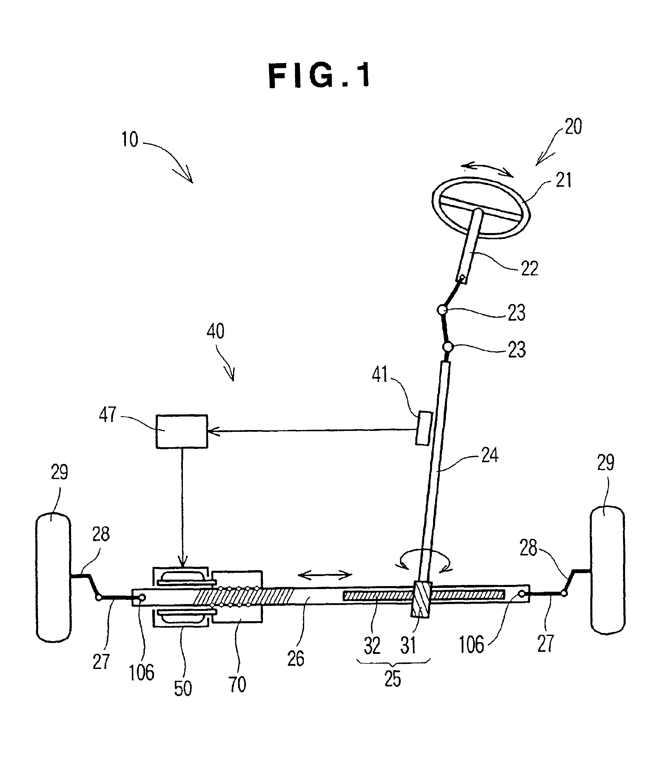
[0040]Referring now to the drawings and FIG. 1 in particular, there is shown the general arrangement of an electric power steering apparatus 10 according to an embodiment of the present invention. The electric power steering apparatus 10 generally comprises a steering system 20 extending from a steering wheel 21 of a vehicle to steerable road wheels 29, 29 and an assist torque mechanism 40 for applying an assist torque to the steering system 20. The illustrated electric power steering apparatus is of the so-called “end take-off type” steering apparatus wherein a steering torque is taken out from opposite ends of a rack shaft 26.

[0041]The steering system 20 includes a steering shaft 22 connected at one end to the steering wheel 21 for co-rotation with the steering wheel 21. The other end of the steering shaft 22 is connected to a pinion shaft 24 via a pair of universal joints 23, 23. The pinion shaft 24 is connected to the rack shaft 26 via a rack-and-pinion mechanism 25. The opposit...


PUM


Abstract

An electric power steering apparatus for a vehicle includes a rack shaft having a rack of gear teeth formed at one end portion thereof and an externally threaded screw formed at a portion thereof excluding the toothed one end portion, a pinion meshing with the rack, a ball-screw mechanism having a nut threadedly engaged with the screw via balls, and an electric motor having a hollow motor shaft extending around the rack shaft and connected to the nut such that an assist torque generated by the electric motor is transmitted from the motor shaft via the nut to the rack shaft. The nut is disposed between the rack and the electric motor. This arrangement ensures that the electric motor and the electric power steering apparatus can be assembled easily and efficiently.

Description

FIELD OF THE INVENTION[0002]The present invention relates to improvements in an electric power steering apparatus carried on a vehicle.BACKGROUND OF THE INVENTION[0003]In recent years, electric power steering apparatuses have increasingly been used to provide a comfortable steering touch or feel to the driver by reducing the manual steering effort or force needed to turn the steering wheel. The electric power steering apparatuses of the type concerned are constructed such that an assist torque generated by an electric motor in proportion to the steering torque is transmitted to the rack shaft of a steering system. A typical example of such known steering apparatuses will be described below with reference to FIGS. 11A and 11B.[0004]As shown in FIGS. 11A and 11B, the conventional electric power steering apparatus 200 includes a rack shaft 201 extending in a transverse direction of the vehicle and having a rack 202 of gear teeth formed at its one end portion, a pinion shaft 203 having ...

Claims


Application Information

Patent Timeline
IPC IPC(8): B62D5/04B62D5/22F16H25/20H02K7/06H02K15/14
CPCB62D5/0427B62D5/043B62D5/0448F16H25/2021H02K7/06
Inventor TOYOFUKU, RYOJIKAWAKAMI, TAKAHIROSUGINO, MITSUTAKATSUTSUI, YASUHIRO
Owner HONDA MOTOR CO LTD
Learn More