Fabrication of a polymeric prosthetic implant

Inactive Publication Date: 2005-02-01
OSTEOPLASTICS +1
View PDF5 Cites 43 Cited by
  • Summary
  • Abstract
  • Description
  • Claims
  • Application Information

AI Technical Summary

Benefits of technology

The present method comprise the following steps: providing a solution comprising chains of a photopolymerizable, bioerodable, liquid polymeric materials (referred to hereinafter as a “primary polymer”) and a photoinitiator for promoting photocrosslinking of the primary polymer; providing a stereolithography instrument comprising a UV laser for activating the photoinitiator and photocrosslinking the primary polymer; providing a CAD image of the desired three-dimensional prosthetic prosthetic implant, wherein said CAD image is readable by the stereolithography instrument; depositing the solution in successive layers on a build platen in the stereolithography instrument; and photocrosslinking the primary pol

Problems solved by technology

Large skeletal defects frequently arise following reconstructive surgery for trauma, cancer resection, infection and congenital deformity.
Although an autograft, typically, does not cause an immune response, it is associated with several disadvantages including donor site morbidity and limited availability.
Furthermore, it is possible that an autograft will not successfully vascularize in the new site, leading to its resorption and/or infection of the graft site.
Unfortunately, the long term persistence of these materials can lead to complications at and surrounding the defect site.
For example, because such materials may have a different modulus and strength than the surrounding tissue, implantation of prosthetic devices made from such materials into the defect site ca

Method used


Image

  • Fabrication of a polymeric prosthetic implant
  • Fabrication of a polymeric prosthetic implant
  • Fabrication of a polymeric prosthetic implant

Examples


example 1

Materials and Methods

The materials used to produce the prosthetic implant were; Poly(propylene fumerate) (PPF) (prepared in the Bioengineering Department, Rice University, Houston, Tex.), Bisacylphosphine Oxide (BAPO) (Irgacure 819) (CIBA Specialty Chemicals Additives Division, Tarrytown, N.Y.), and Chloroform C-295 (Fisher Scientific, Fair Lawn, N.J.). Materials were weighed and mixed in a standard fume cabinet; One gm of BAPO was dissolved in 10 gm of chloroform and mixed thoroughly, 0.5 ml of the BAPO / chl mixture was added to 10 gm of PPF and mixed thoroughly. The resulting resin mixture was poured into a 3½-inch diameter culture dish to a depth of 2 mm.

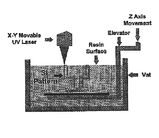
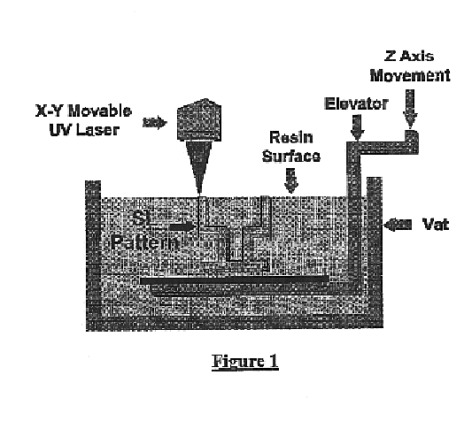
The stereolithography machine (3D Systems SLA 250, Valencia, Calif.) consists of a servomechanism, which controls the beam of a UV laser in the X and Y horizontal axis, a tank of liquid monomer resin, and a motorized build platform moving in the Z-axis (i.e., vertically up and down in the tank of resin). A build platen is located ...

example 2

Materials and Methods

The materials used to prepare the device were; Poly(propylene fumarate) (PPF) (Rice University-Bioengineering Department, Houston, Tex.), Diethyl fumarate (DEF) solvent, (Fisher Scientific, Fairlawn, N.J.), Bisacylphosphine Oxide (BAPO) photoiniator (Irgacure 819) (CIBA Speciality Chemicals Additives Division, Tarrytown, N.Y.). Materials were weighed and mixed in a standard fume cabinet. Two grams of BAPO were dissolved in 200 g of DEF and mixed thoroughly. The BAPO / DEF mixture was then added to 280 g of PPF and mixed thoroughly. The quantities of DEF and PPF used resulted in a mixture that had similar viscosity properties to the native resin normally used with the SLA machine. The DEF / PPF resin was allowed to stand for 30 minutes to allow air bubbles trapped in the mixture to dissipate.

Method

The stereolithography machine used was an SLA 250 / 40 (3D Systems Valencia, Calif.). The SLA 250 / 40 consists of a servomechanism, which controls the beam of a UV laser in th...


PUM

PropertyMeasurementUnit
Thicknessaaaaaaaaaa
Diameteraaaaaaaaaa
Photocurableaaaaaaaaaa

Abstract

Processes for fabricating a customized, three-dimensional, bioerodable, polymeric prosthetic implant are provided. In a highly preferred embodiment, the prosthetic implant has a porous network. The method employs a sterolithography instrument, a solution comprising chains of one or more photocurable, bioerodable polymers and a photoinitiator, and a three-dimensional CAD image. In a highly preferred embodiment, the solution comprises poly (propylene) fumarate (PPF) and a solvent for controlling the viscosity of the solution. During the fabrication process, the solution is placed in a container in the stereolithography instrument. The container also holds a movable build platen for supporting each of the covalently bonded layers of the polymeric prosthetic implant that are formed when successive layers of the solution are exposed to UV light energy. The UV light energy is imparted to selected portions of each layer of the solution to produce a pattern of cross-linked and non-cross-linked polymeric regions corresponding to a cross-sectional image of the three-dimensional CAD image.

Description

BACKGROUND OF THE INVENTIONLarge skeletal defects frequently arise following reconstructive surgery for trauma, cancer resection, infection and congenital deformity. The standard clinical treatment for these defects is the transplantation of a bone graft derived from the patient (autograft) into the defect site. Although an autograft, typically, does not cause an immune response, it is associated with several disadvantages including donor site morbidity and limited availability. Furthermore, it is possible that an autograft will not successfully vascularize in the new site, leading to its resorption and / or infection of the graft site.Other treatments may be used to replace the defect. These include implantation of a bone cement (calcium phosphate, acrylic [e.g., PMMA], or plastic [e.g., polyethylene]) or a metal prosthetic. Unfortunately, the long term persistence of these materials can lead to complications at and surrounding the defect site. For example, because such materials may...

Claims


Application Information

Patent Timeline
IPC IPC(8): A61F2/30A61F2/28A61L27/00A61L27/48A61L27/18A61L27/56B29C67/00G05B19/4097G05B19/4099A61B17/86A61B17/68A61F2/00A61F2/02
CPCA61F2/28A61F2/30942A61L27/18A61L27/48A61L27/56B29C67/0055B29C67/0066B29C67/0092G05B19/4099C08L67/06C08L67/04A61B17/866Y10T156/109A61F2002/30062A61F2002/30199A61F2002/30948A61F2002/30952A61F2002/30962A61F2210/0004A61F2230/0063B29K2995/0073G05B2219/45172A61B2017/568B29C64/135B29C64/40B33Y80/00B33Y50/00B33Y70/00B33Y10/00
Inventor DEAN, DAVIDCOOKE, MALCOLM
Owner OSTEOPLASTICS
Why Eureka
Try Eureka