Low-temperature fuel cell

a fuel cell and low-temperature technology, applied in the field of low-temperature fuel cells, can solve the problems of difficult deformation, difficult mechanical deformation, and relatively brittleness of interconnector plates of this type, and achieve the effects of simple bending, easy mechanical deformation, and successful discharge of current and hea

Inactive Publication Date: 2005-02-01
SIEMENS ENERGY GLOBAL GMBH & CO KG
View PDF11 Cites 25 Cited by
  • Summary
  • Abstract
  • Description
  • Claims
  • Application Information

AI Technical Summary

Benefits of technology

An interconnector plate assembled in this manner is very resistant to corrosion caused by oxygen even in combination with water and at elevated temperatures. Moreover, an interconnector plate of this type is very easy to deform mechanically. For example, it can be converted into the desired shape by simple bending without any cracks being formed and desired shapes, channels or spacers can be formed into it, by way of example, by the deep-drawing process. Moreover, an interconnector plate made from the abovementioned materials can be welded successfully by means of various processes and can easily be connected in a gastight manner to adjacent components.
A further advantage which should be mentioned is that the interconnector plate is gastight and does not become brittle in a hydrogen environment. Moreover, it is particularly successful at discharging current and heat.
In an advantageous configuration of an embodiment of the invention, the interconnector plate includes two metal sheets which form a cavity, in which case the interconnector plate, in an expedient configuration, may include substantially only the metal sheets which form the cavity. The abovementioned choice of material for the interconnector plate indicates that it is not necessary to produce the interconnector plate in a compact form for stability reasons. Moreover, the material used for the interconnector plate is sufficiently hard and elastic for two thin metal sheets which form a cavity to impart sufficient stability to the interconnector plate. The cavity may in this case be designed with feed and discharge passages, in such a manner that while the fuel cell is operating it serves as a cooling water space through which cooling water or heating water flows. This is particularly advantageous especially for low-temperature fuel cells, since in fuel cells of this type considerable amounts of heat have to be dissipated from the fuel cell. An interconnector plate which comprises two metal sheets forming a cavity and through which cooling water flows solves this problem in a simple and effective way. Moreover, the interconnector plate has sufficient stability to be able to cope with even pressurized cooling water without there being any risk of cracks or leaks being formed.
In the region of the cavity, the metal sheets expediently have a thickness of between 0.08 mm and 0.3 mm. The abovementioned particular choice of material makes it possible to produce the metal sheets for the interconnector plate in a particularly thin form yet with sufficient stability. Moreover, the elasticity and simultaneous tensile strength of the material prevents the cavity of the interconnector plate from exploding even when there is a pressure difference of a few bar between the environment inside the cavity and the environment outside the cavity. The extremely low thickness of the metal sheets means that particularly good heat transfer between the gas spaces and the cavity in the interconnector plate is ensured.
In a further advantageous configuration of an embodiment of the invention, the low-temperature fuel cell is suitable for operation with pure oxygen and pure hydrogen. An interconnector plate as described above has very good resistance to corrosion even with respect to moist pure oxygen and pure hydrogen.

Problems solved by technology

In particular in the case of operation with pure oxygen and pure hydrogen, the interconnector plate is exposed to extremely corrosive operating gases.
However, an interconnector plate of this type has the drawback of being relatively brittle.
It is therefore difficult to deform and has very poor welding properties, and moreover must be made relatively thick if the required stability is to be achieved.

Method used


Image

  • Low-temperature fuel cell
  • Low-temperature fuel cell

Examples


Embodiment Construction

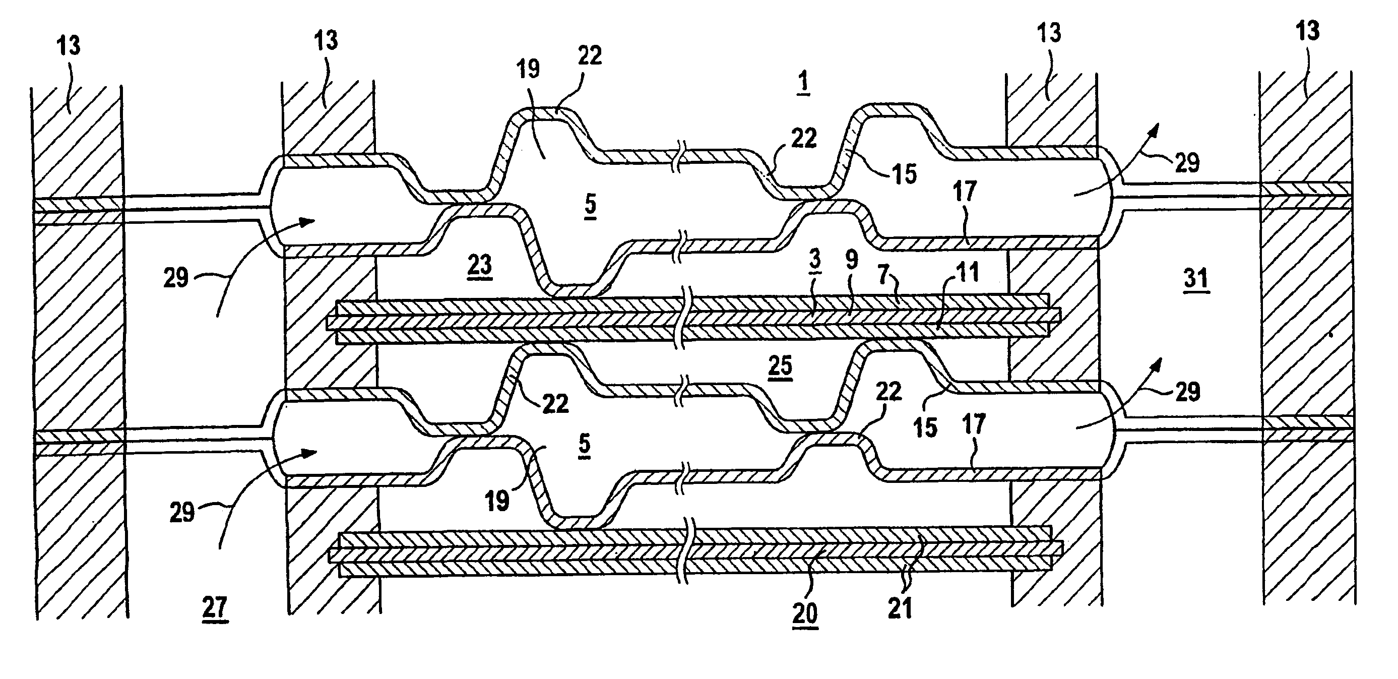
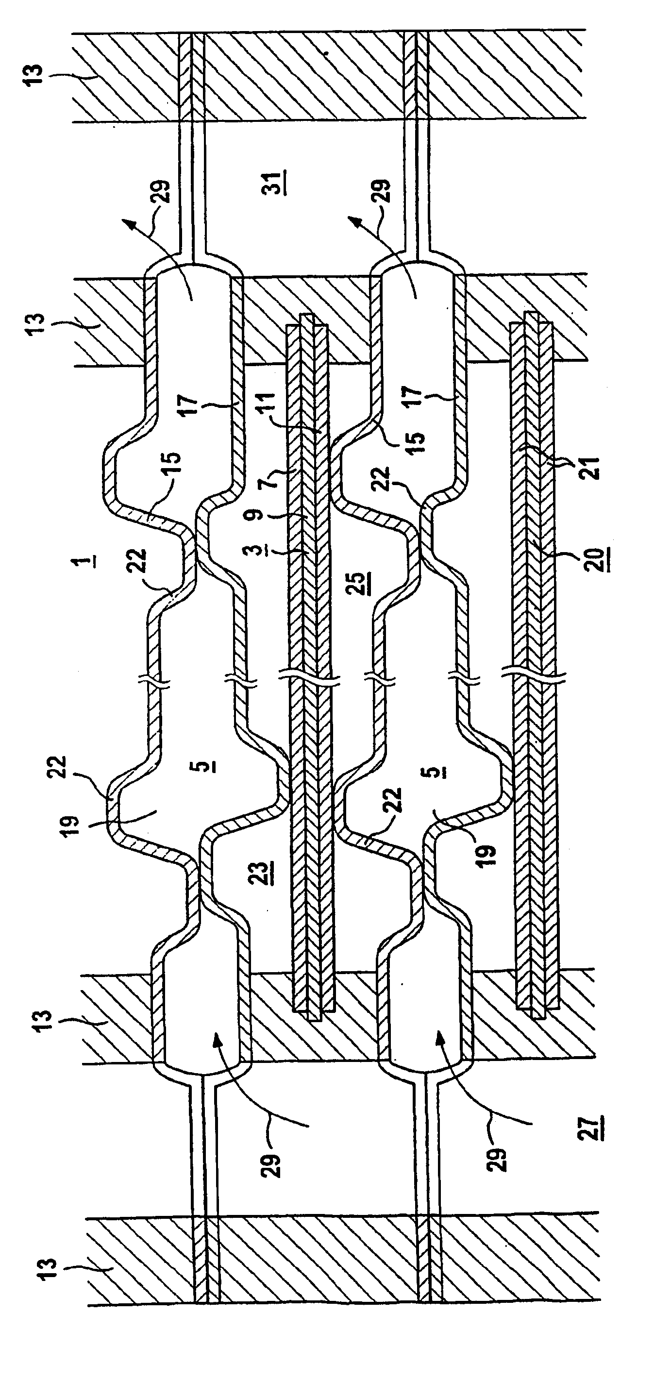
An exemplary embodiment of the invention is explained with reference to a FIGURE. The FIGURE diagrammatically depicts a section through a low-temperature fuel cell 1, which includes an electrolyte electrode assembly 3 and two interconnector plates 5 which adjoin the electrolyte electrode assembly 3. The electrolyte electrode assembly 3 includes an anode 7, an electrolyte 9 and a cathode 11. The electrolyte electrode assembly 3 and the interconnector plates 5 are mounted in seals 13. The interconnector plates 5 each include two metal sheets 15, 17, which between them form a cavity 19. Adjacent to the low-temperature fuel cell 1 there is a further low-temperature fuel cell, which likewise comprises an electrolyte electrode assembly 20 with two electrodes 21.

The two metal sheets 15, 17 of the interconnector plates 5 each contain 57% of nickel, 16% of molybdenum, 15% of chromium, 5% of iron, 4% of tungsten, 1.5% of cobalt, 0.5% of manganese and 1% of other metals and impurities. The two...


PUM

PropertyMeasurementUnit
thicknessaaaaaaaaaa
thicknessaaaaaaaaaa
temperatureaaaaaaaaaa

Abstract

The composite conductor plate of a low-temperature fuel cell poses the following problem: it must be extremely corrosion-resistant to pure oxygen that is humidified by water and to pure hydrogen and must at the same time be able to be processed mechanically. To solve the problem, a composite conductor plate contains 50 to 60 wt. % Ni, 12 to 22 wt. % Cr, 10 to 18 wt. % Mo, 4 to 10 wt. % Fe and 0.5 to 5 wt. % W.

Description

FIELD OF THE INVENTIONThe invention generally relates to a low-temperature fuel cell. Preferably, it relates to one having an electrode and an interconnector plate, which electrically connects the electrode to an electrode of an adjacent low-temperature fuel cell.BACKGROUND OF THE INVENTIONIn a fuel cell, electrical energy and heat am generated by bringing together hydrogen (H2) and oxygen (O2) in an electrochemical reaction. For this purpose, hydrogen and oxygen are fed to the fuel cell, either in their pure form or as fuel gas containing hydrogen and as air. The type of operating gases which are fed to the fuel cell is substantially dependent on the operating environment in which the fuel cell is operated. A fuel cell of a fuel cell system which is operated, for example, in a hermetically sealed space is usually operated with pure oxygen and pure hydrogen. While the fuel cell is operating, these operating gases react to form water (H2O) substantially without any residue, with the ...

Claims


Application Information

Patent Timeline
Patent Type & Authority Patents(United States)
IPC IPC(8): H01M8/02C22C19/05H01M8/0208H01M8/0228H01M8/0254H01M8/0267
CPCH01M8/0208H01M8/0228H01M8/0254Y02E60/50H01M8/0267H01M8/0271
Inventor HARTNACK, HERBERTLERSCH, JOSEFMATTEJAT, ARNOSTRASSER, KARL
Owner SIEMENS ENERGY GLOBAL GMBH & CO KG
Why Eureka
Try Eureka