
Photoresists, polymers and processes for microlithography

a technology of microlithography and polymer, applied in the field of photoimaging, can solve the problems of not teaching that the compositions disclosed could be used in photoresists, and the use of copolymers is not disclosed. achieve the effects of high plasma etch resistance, good balance of desirable properties, and high transparency

Inactive Publication Date: 2005-02-01
EI DU PONT DE NEMOURS & CO
View PDF73 Cites 221 Cited by
  • Summary
  • Abstract
  • Description
  • Claims
  • Application Information

AI Technical Summary

Benefits of technology

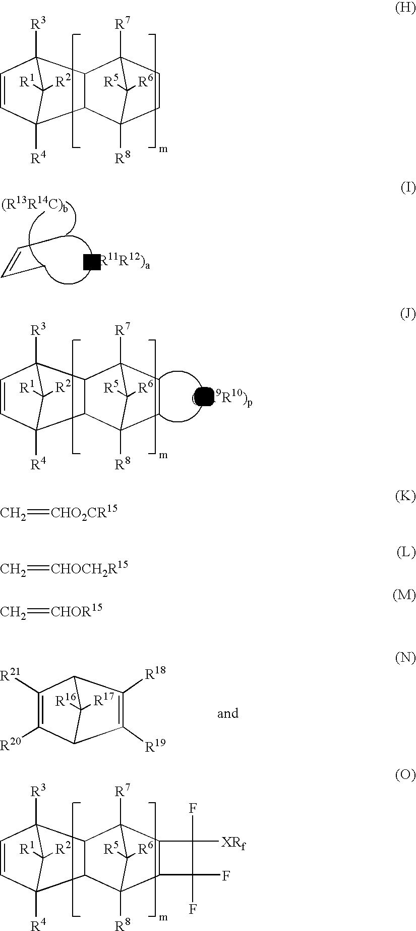
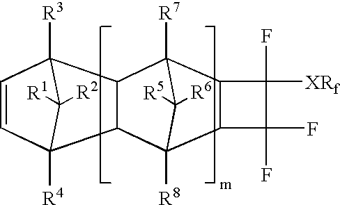
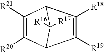
In certain embodiments of this invention, the fluorine-containing copolymer may be comprised of a repeat unit derived from at least one polycyclic ethylenically unsaturated compound having at least one atom or group selected from the group consisting of fluorine atom, perfluoroalkyl group, and perfluoroalkoxy group, covalently attached to a carbon atom which is contained within a ring structure. Fluorine atoms, perfluoroalkyl groups and perfluoroalkoxy groups tend to inhibit polymerization of cyclic ethylenically unsaturated compounds by metal-catalyzed addition polymerization or metathesis polymerization when such groups are attached directly to an ethylenically unsaturated carbon atom. Thus, it is critical in such cases that the at least one fluorine atom, perfluoroalkyl group and perfluoroalkoxy group be separated from each ethylenically unsaturated carbon atom of the ethylenically unsaturated compound by at least one covalently attached carbon atom. Furthermore, attaching the atom and / or group directly to a ring minimizes the presence of undesirable non-fluorinated aliphatic carbon atoms.
The photoresist compositions of this invention have a particularly good balance of desirable properties, including high transparency to extreme, far, and near ultraviolet light, high plasma etch resistance, and projected high resolution characteristics suitable for microelectronics device fabrication using 0.18 and 0.13 μm design rules. The photoresist compositions of this invention in particular have good optical transparency at 157 nm. The novel copolymers of this invention also have good properties including anticipated high transparency at 157 nm and other wavelengths in the UV.

Problems solved by technology

These patents do not disclose the use of these copolymers in any photosensitive compositions.
Furthermore, there is no teaching that the compositions disclosed could be used in photoresists with imaging effected at far UV wavelengths of less than 180 nm.

Method used


Image

  • Photoresists, polymers and processes for microlithography
  • Photoresists, polymers and processes for microlithography
  • Photoresists, polymers and processes for microlithography

Examples


example 1

Synthesis of TFE / Norbornene Copolymer=P(TFE / NB)

A 1-L stirred Hastelloy autoclave was charged with a solution of 28.2 g (0.30 mol) norbornene in 300 mL CFC-113. The autoclave was closed, pressured to 200 psi with nitrogen three times, cooled and evacuated. TFE (35 g, 0.35 mol) was added and the mixture was heated with stirring to 40° C. A 25 mL portion of a solution of 5.0 g of 60% di(sec-butyl)peroxydicarbonate in 50 mL of CFC-113 was injected over 5 min. The resulting mixture was stirred for about 18 hr. The reactor was cooled, vented and the clear colorless solution was removed using CFC-113 to rinse. Polymer was isolated by precipitation of the CFC-113 solution into excess methanol. The white solid was filtered and dried in a vacuum oven overnight at about 45° C. Isolated yield was 7.4 g of white polymer; GPC (MEK) Mw 2800, Mn 1700, Mw / Mn 1.59; Inh. Visc. 0.0271 (MEK). Anal. Found: C, 54.27; H, 5.28; F, 30.81. From the % H, the composition of the polymer was calculated as 49 mol ...

example 2

Synthesis of TFE / Norbornene Copolymer=P(TFE / NB)

A 400 mL stainless steel pressure vessel was charged with a solution of 33 g (0.35 mol) norbornene in 120 mL of CFC-113. Perkadox® 16 N (1.20 g) was added. The vessel was closed, purged with nitrogen, cooled, evacuated and charged with 40 g (0.40 mol) TFE. The vessel was heated with shaking to 50° C. and maintained for 18 hr with the internal pressure decreasing from 200 psi to 167 psi. The vessel was cooled, vented and the liquid contents recovered using additional CFC-113 to rinse. Polymer was isolated by precipitation of the CFC-113 solution into excess methanol. The white solid was filtered and dried in a vacuum oven overnight at about 65° C. Isolated yield was 29.7 g (41%) of white polymer; GPC (MEK) Mw 10000, Mn 2900, Mw / Mn 3.57; Inh. Visc. 0.0130 (MEK). Anal. Found: C, 54.60; H, 5.05; F, 31.21. From the % C, the composition of the polymer was calculated as 52 mol % TFE and 48 mol % norbornene.

example 3

Synthesis of TFE / Norbornene Copolymer=P(TFE / NB)

The procedure of Example 2 was followed using 47 g (0.5 mol) norbornene, 120 mL CFC-113, 1.6 g Perkadox® 16N and 50 g (0.50 mol) TFE with polymerization conducted at 40° C. for 18 hr. There was isolated 19.7 g (20%) of white polymer; GPC (MEK) Mw 10600, Mn 3700; Mw / Mn 2.89; Inh. Visc. 0.0195 (MEK); Tg 152° C. (DSC). Anal. Found: C, 58.33; H, 5.63; F, 33.13. From the % C analysis, composition of the polymer was calculated as 46 mol % TFE and 54 mol % norbornene.


PUM

PropertyMeasurementUnit
Nanoscale particle sizeaaaaaaaaaa
Wavelengthaaaaaaaaaa

Abstract

Photoresists and associated processes for microlithography in the extreme, far, and near UV are disclosed. The photoresists in some embodiments comprise (a) a fluorine-containing copolymer derived from at least one polycyclic ethylenically unsaturated compound and at least one compound having at least one fluorine atom covalently attached to an ethylenically unsaturated carbon atom; and (b) at least one photoactive component. In other embodiments, the photoresists comprise a fluorine-containing copolymer derived from at least one polycyclic ethylenically unsaturated compound having at least one atom or group covalently attached to a carbon atom contained within a ring structure and separated from each ethylenically unsaturated carbon atom of the ethylenically unsaturated compound by at least one covalently attached carbon atom, wherein the atom or group is selected from the group consisting of fluorine perfluoroalkyl and perfluoroalkoxy.

Description

BACKGROUND OF THE INVENTION1. Field of the InventionThe present invention pertains to photoimaging and, in particular, the use of photoresists (positive-working and / or negative-working) for imaging in the production of semiconductor devices. The present invention also pertains to novel fluorine-containing polymer compositions which are useful as base resins in resists and potentially in many other applications.2. Description of Related ArtPolymer products are used as components of imaging and photosensitive systems and particularly in photoimaging systems such as those described in Introduction to Microlithography, Second Edition by L. F. Thompson, C. G. Willson, and M. J. Bowden, American Chemical Society, Washington, D.C., 1994. In such systems, ultraviolet (UV) light or other electromagnetic radiation impinges on a material containing a photoactive component to induce a physical or chemical change in that material. A useful or latent image is thereby produced which can be process...

Claims


Application Information

Patent Timeline
IPC IPC(8): C08F214/18C08F214/00G03F7/20G03F7/30G03C1/73G03F7/038G03F7/039
CPCG03F7/0046G03F7/0395G03F7/0397G03F7/322C08F214/26C08F214/182C08F214/24G03F7/325Y10S430/108Y10S430/115
Inventor FEIRING, ANDREW E.SCHADT, III, FRANK L.
Owner EI DU PONT DE NEMOURS & CO
Learn More