System and method for clamp current regulation of induction machines

a clamp current and clamp current technology, applied in the field of electrical machines, can solve the problems of increasing the cost of the drive system, creating numerous and cumbersome data structures, etc., and achieve the effects of preventing current loss, maximizing machine efficiency, and producing maximum torqu

Inactive Publication Date: 2005-02-01
DELPHI TECH IP LTD
View PDF5 Cites 32 Cited by
  • Summary
  • Abstract
  • Description
  • Claims
  • Application Information

AI Technical Summary

Benefits of technology

The invention is based upon the discovery that in current control for induction machines, a limiter in the current regulator of a proportional integral control that clamps the current regulators at the available voltage vector with appropriate phase preventing loss of current regulation, maximizes the efficiency of the machine and produces maximum torque in the field weakening region. The arrangement is capable of adjusting to the true base speed of the machine as the DC-link voltage varies.
The method according to the invention limits current regulators to an available voltage magnitude, voltage angle delta and a slip frequency range for assuring that the system does not exceed the available voltage and that the machine efficiency is maximized and that maximum torque is produced in the field-weakening region.

Problems solved by technology

This would undesirably add incremental costs to the drive system.
However, the use of look-up tables requires the creation of numerous and cumbersome data structures within the look-up tables themselves to handle all possible situations in the system and its environment.

Method used


Image

  • System and method for clamp current regulation of induction machines
  • System and method for clamp current regulation of induction machines
  • System and method for clamp current regulation of induction machines

Examples


Embodiment Construction

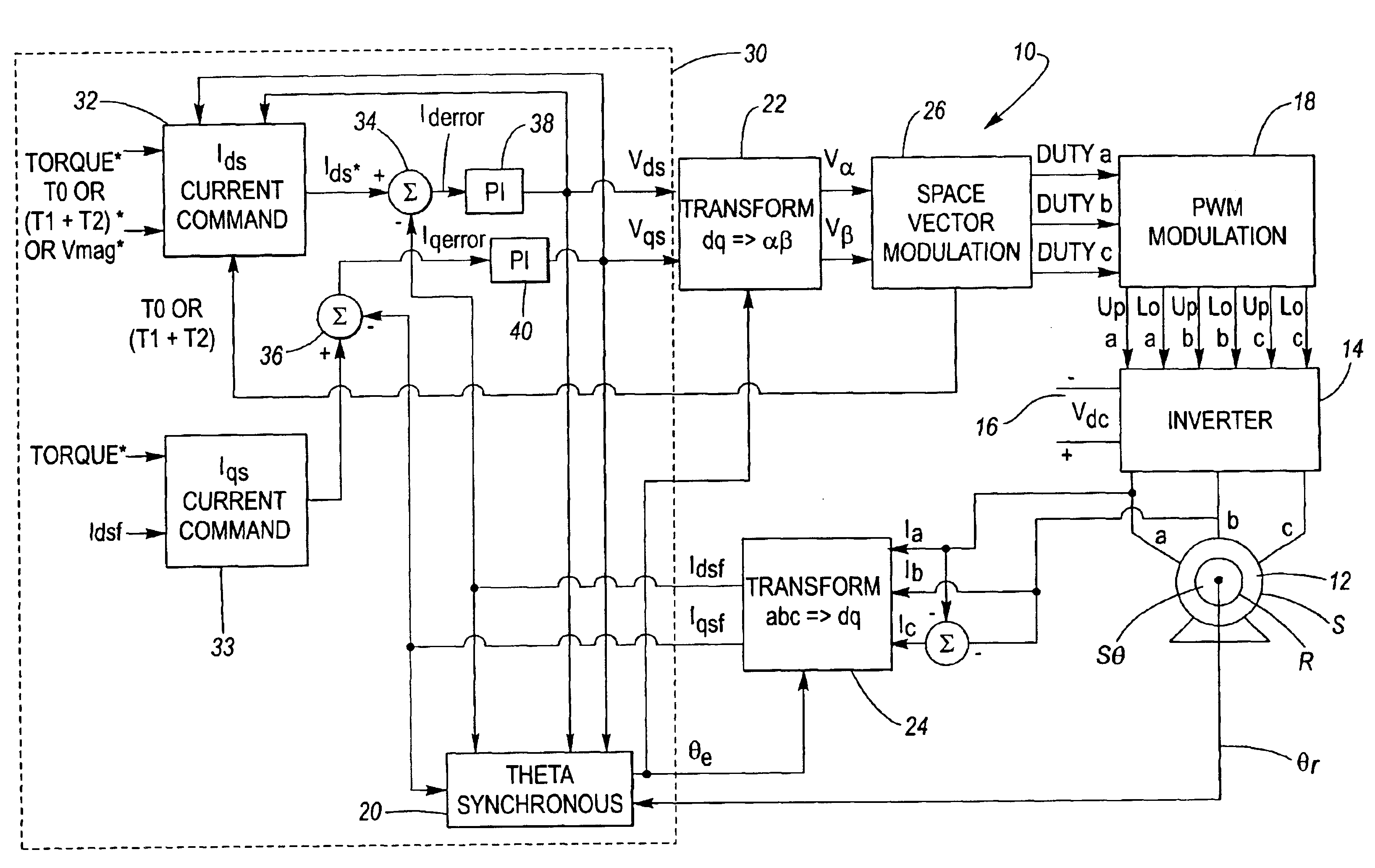
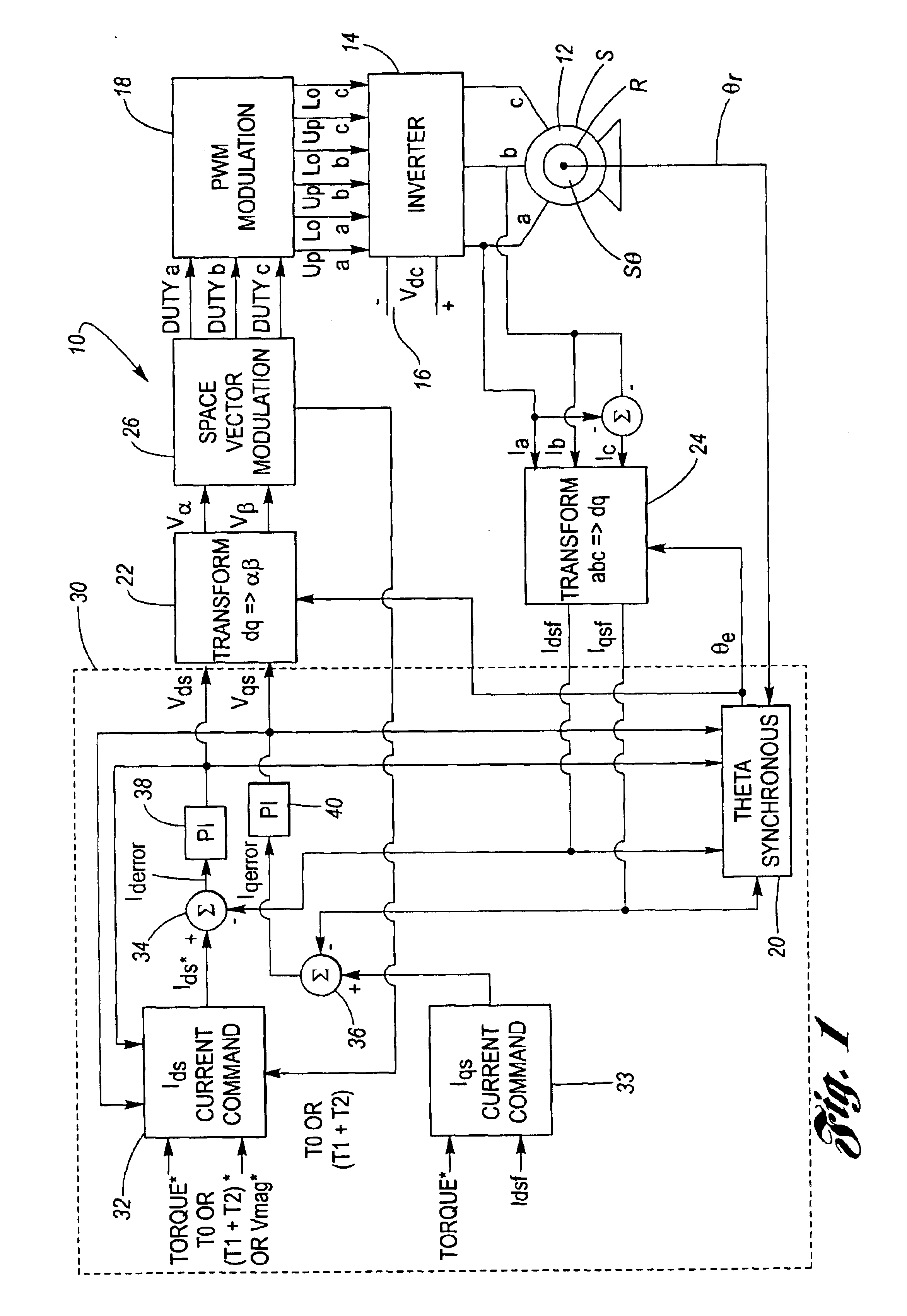
The invention is directed to a method and apparatus for current control in induction machines. The method is specifically designed to produce additional functionality in the field-weakening region.

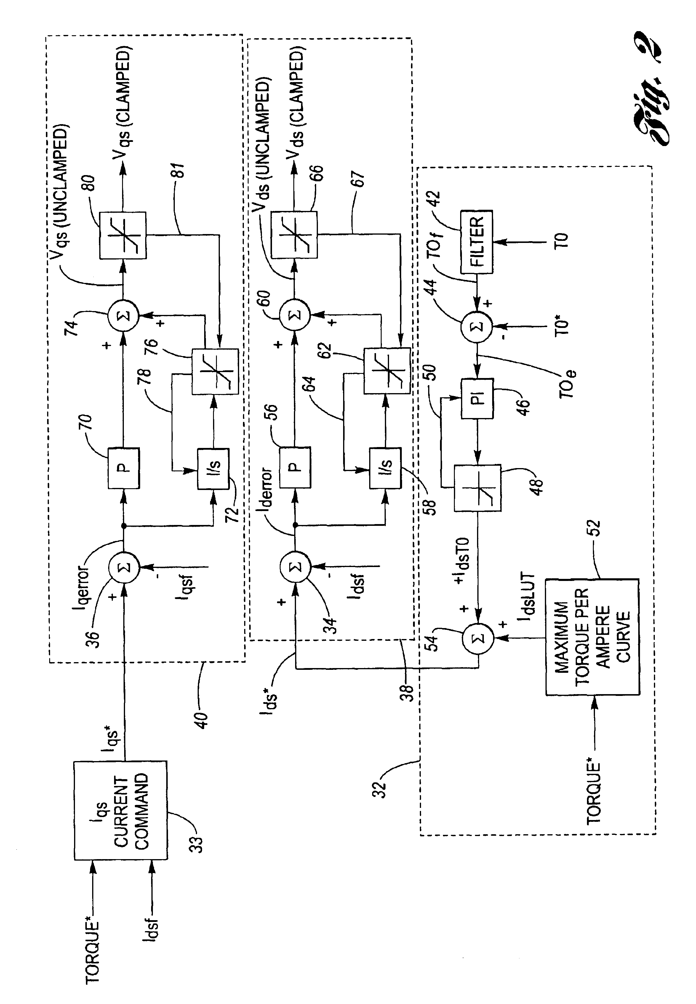
To extend the operational speed range of induction machines, it is necessary to de-flux the machine by applying reduced current in the synchronous D-axis, Ids. The advantage of the method is that it applies the appropriate amount of current at each operating point across the entire speed range of the machine, that is, in the constant torque region and in the field-weakening region.

An important feature of the invention is that when the current regulator exceeds the available voltage, the system decreases Ids. Furthermore, when the voltage angle exceeds the maximum voltage angle delta for motoring mode, or is less than the minimum voltage angle delta for generating mode, the system clamps the angle to the maximum delta angle for motoring mode or the minimum delta angle for generating mode, a...


PUM


Abstract

A device to regulate current produced by an induction machine responsive to a plurality of phase current signals. The motor produces torque for application on a shaft. A processing and drive circuit responsive to a direct current command signal and a quadrature current command signal produces phase current signals for input to the motor. A command circuit responsive to the phase current signals, an angular position of said shaft, and a voltage input command signal to produce a direct current error signal and a quadrature current error signal. A control circuit responsive to the direct and quadrature current error signals produces the direct voltage signal command and the quadrature signal command. The control circuit has a direct and quadrature proportional gain, integrator and clamp circuits. An algorithm produces limited or clamped voltage modulation index signals to obtain maximum efficiency and maximum torque per ampere in the speed range.

Description

BACKGROUND OF THE INVENTION1. Technical FieldThe present invention is directed generally to electromechanical machines, and, in particular, to a system and a method for current regulation in the field-weakening operation of induction machines.2. Description of the Related ArtIn the control of inverter-driven induction machines, field weakening is often used to lower the inverter voltage rating for a given application. Without field weakening the inverter manufacturer would have to use components rated to handle higher levels of voltage for that given application. This would undesirably add incremental costs to the drive system. During high speed operation, the phase current may be applied to the machine windings in advance of the phase electromotive force. To control the electromotive force, the D axis current is decreased inversely with speed.It is known to provide a flux weakening algorithm by the use of a number of look-up tables to produce the reference Q-axis and D-axis current...

Claims


Application Information

Patent Timeline
Patent Type & Authority Patents(United States)
CPCH02P21/0089H02P21/06H02P2207/01H02P2205/01H02P21/00
Inventor GALLEGOS-LOPEZ, GABRIELGUNAWAN, FANI S.WALTERS, JAMES E.
Owner DELPHI TECH IP LTD
Why Eureka
Try Eureka