Light diffusing plate, optical element, and liquid-crystal display

a technology of light diffusing plate and liquid crystal display, which is applied in the direction of optical elements, polarising elements, instruments, etc., can solve the problems of inapplicability to reflection type, inability to produce light diffusing plate, and inapplicability to conventional system to reflect type, etc., to achieve excellent thermal and chemical stability and suitability for practical use, easy production, and less absorbability

Inactive Publication Date: 2005-02-01
NITTO DENKO CORP
View PDF15 Cites 18 Cited by
  • Summary
  • Abstract
  • Description
  • Claims
  • Application Information

AI Technical Summary

Benefits of technology

An object of the present invention is to provide a light diffusing plate which is easily producible and excellent in thermal and chemical stability and suitability for practical use, is capable of supplying linearly polarized light less absorbable by a polarizing plate and of thus improving brightness, is less apt to pose the problem of coloration, and is applicable also to reflection type liquid-crystal displays and the like. Another object of the present invention is to provide an optical element and a liquid-crystal display each employing the light diffusing plate.
In the light diffusing plate in the present invention, the minute regions and the matrix dispersedly containing the same each is made of a polymeric material. Consequently, the light diffusing plate not only is excellent in raw-material handleability and easily producible but has excellent stability of optical functions and excellent suitability for practical use due to the thermal and chemical stability of those materials. Furthermore, in the axis direction (Δn2 direction) in which a linearly polarized light has a maximum transmittance, the linearly polarized light passes through the diffusing plate while satisfactorily retaining its polarized state. In directions (Δn1 directions) perpendicular to the An2 direction, the linearly polarized light is scattered based on the difference in refractive index Δn1 between the birefringent film and the minute regions, whereby the polarized state is diminished or eliminated.
Consequently, by disposing the light diffusing plate and a polarizing plate so that the transmission axis of the polarizing plate is parallel to the Δn2 direction, the Δn2 direction-transmittable, linearly polarized light efficiently passes through the polarizing plate and the Δn1 direction-transmittable, linearly polarized light is scattered. As a result, the polarization direction is changed, and linearly polarized light components containing Δn2 direction-transmittable ones pass through the polarizing plate.
The above constitution therefore brings about an increase in the amount of linearly polarized light passing through the polarizing plate, and this effect functions like the reduction of absorption loss to attain an improvement in the brightness of transmission type liquid-crystal displays or the like. Furthermore, the above constitution is less apt to pose the problem of coloration caused by large wavelength dependence such as that of cholesteric liquid crystals, and can be easily applied also to reflection type liquid-crystal displays. Thus, a liquid-crystal display excellent in brightness and perceptibility can be obtained at low cost.

Problems solved by technology

These problems are that the large wavelength dependence of the cholesteric liquid crystal causes coloration of, in particular, obliquetransmitted light, and that the conventional system is inapplicable to reflection type liquid-crystal displays or the like.
However, the conventional light diffusing plates described above are unsuitable for practical use, for example, because they are difficult to produce and because when applied to liquid-crystal displays or the like, the diffusing plates have poor handleability and poor stability of functions.

Method used


Image

  • Light diffusing plate, optical element, and liquid-crystal display
  • Light diffusing plate, optical element, and liquid-crystal display
  • Light diffusing plate, optical element, and liquid-crystal display

Examples


example 1

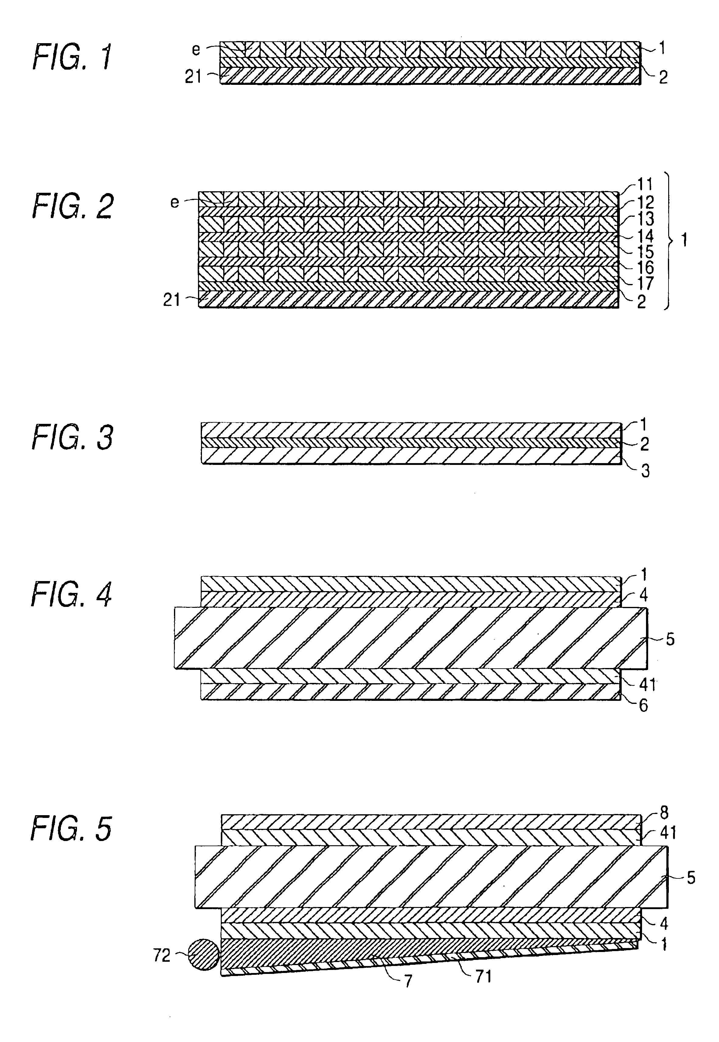
A 20 wt % dichloromethane solution containing 900 parts (parts by weight; the same applies hereinafter) of a norbornene resin (Arton, manufactured y JSR Co., Ltd.) was mixed with 100 parts of a liquid-crystal polymer represented by the following formula. This mixture was used to obtain a 100 μm-thick film by casting. This film was stretched at 175° C. in a stretch ratio of 3. Thus, a light diffusing plate was obtained which consisted of a birefringent film having a refractive index difference Δn1 of 0.230 and a refractive index difference Δn2 of 0.029.

The birefringent film consisted of the norbornene resin as a film base and the liquid-crystal polymer dispersed therein as domains elongated along the stretch direction. The average diameter of these domains was measured through an examination with a polarizing microscope based on coloration by phase difference. As a result, the Δn1 direction length thereof was found to be about 6 μm.

example 2

Two birefringent films which were the same as that obtained in Example 1 were superposed and bonded to each other through a 20 μm-thick acrylic pressure-sensitive adhesive layer so that these films coincided with each other in Δn2 direction. Thus, a light diffusing plate was obtained.

example 3

A light diffusing plate was obtained in the same manner as in Example 1, except that a liquid-crystal polymer represented by the following formula was used. The light diffusing plate thus obtained consisted of a birefringent film having a Δn1 of 0.180 and a Δn2 of 0.032. In copolymerization for producing the liquid-crystal polymer, a monomer corresponding to units “a” and one corresponding to units “b” were used in amounts of 45 parts and 55 parts, respectively. The birefringent film consisted of the norbornene resin as a film base and the liquid-crystal polymer dispersed therein as domains elongated along the stretch direction (Δn1-direction length; about 6 μm).


PUM

PropertyMeasurementUnit
lengthaaaaaaaaaa
transmittanceaaaaaaaaaa
thicknessaaaaaaaaaa

Abstract

A light diffusing plate is formed of a birefringent film containing dispersed therein minute regions differing from the birefringent film in birefringent characteristics. The minute regions are formed of a thermoplastic liquid-crystal polymer. The difference in refractive index between the birefringent film and the minute regions in a direction perpendicular to the axis direction in which a linearly polarized light has a maximum transmittance, Δn1, is 0.03 or larger and that in said axis direction, Δn2, is not larger than 80% of the Δn1. An optical element is formed of a multilayer structure of the above light diffusing plate and at least either of a polarizing plate and a phase plate. A liquid-crystal display is formed of a liquid-crystal cell and, disposed on one or each side thereof, either the above light diffusing plate or the above optical element.

Description

BACKGROUND OF THE INVENTION1. Field of the InventionThe present invention relates to a light diffusing plate which has anisotropy in the scattering of linearly polarized light, is highly effective in diffusing the directions of the scattering thereof, and is suitable for use in, e.g., improving the perceptibility, brightness, and other performances of liquid-crystal displays and the like. This invention further relates to an optical element employing the light diffusing plate.The present application is based on Japanese Patent Application No. Hei. 10-376394 which is incorporated herein by reference.2. Description of the Related ArtConventionally known light diffusing plates which comprise a matrix and, dispersedly contained therein, regions having anisotropy in refractive index and which are anisotropic with respect to the scattering of linearly polarized light include a diffusing plate comprising a combination of a thermoplastic resin and a low-molecular liquid crystal, one compris...

Claims


Application Information

Patent Timeline
Patent Type & Authority Patents(United States)
IPC IPC(8): G02B5/30G02F1/13G02F1/1335G02B5/02G02F1/13363
CPCG02B5/3008G02B5/3016G02F1/13363G02F2413/09G02F2413/04G02F1/133631
Inventor MIYATAKE, MINORUSAKURAMOTO, TAKAFUMI
Owner NITTO DENKO CORP
Why Eureka
Try Eureka