[0020]Advantageously, the invention allows a data link to be operated at increased bit rates of between ten and potentially one hundred times as great as with conventional links, when thermal
noise is a dominant source of bit errors. The invention can allow a data link to be operated at substantially increased bit rates compared with conventional links, when thermal
noise is not a dominant source of bit errors. Moreover, transmitters and receivers embodying the invention may be implemented simply and inexpensively.
[0024]In accordance with another aspect of the present invention, a method of transmitting data across a data link with a less than nominal
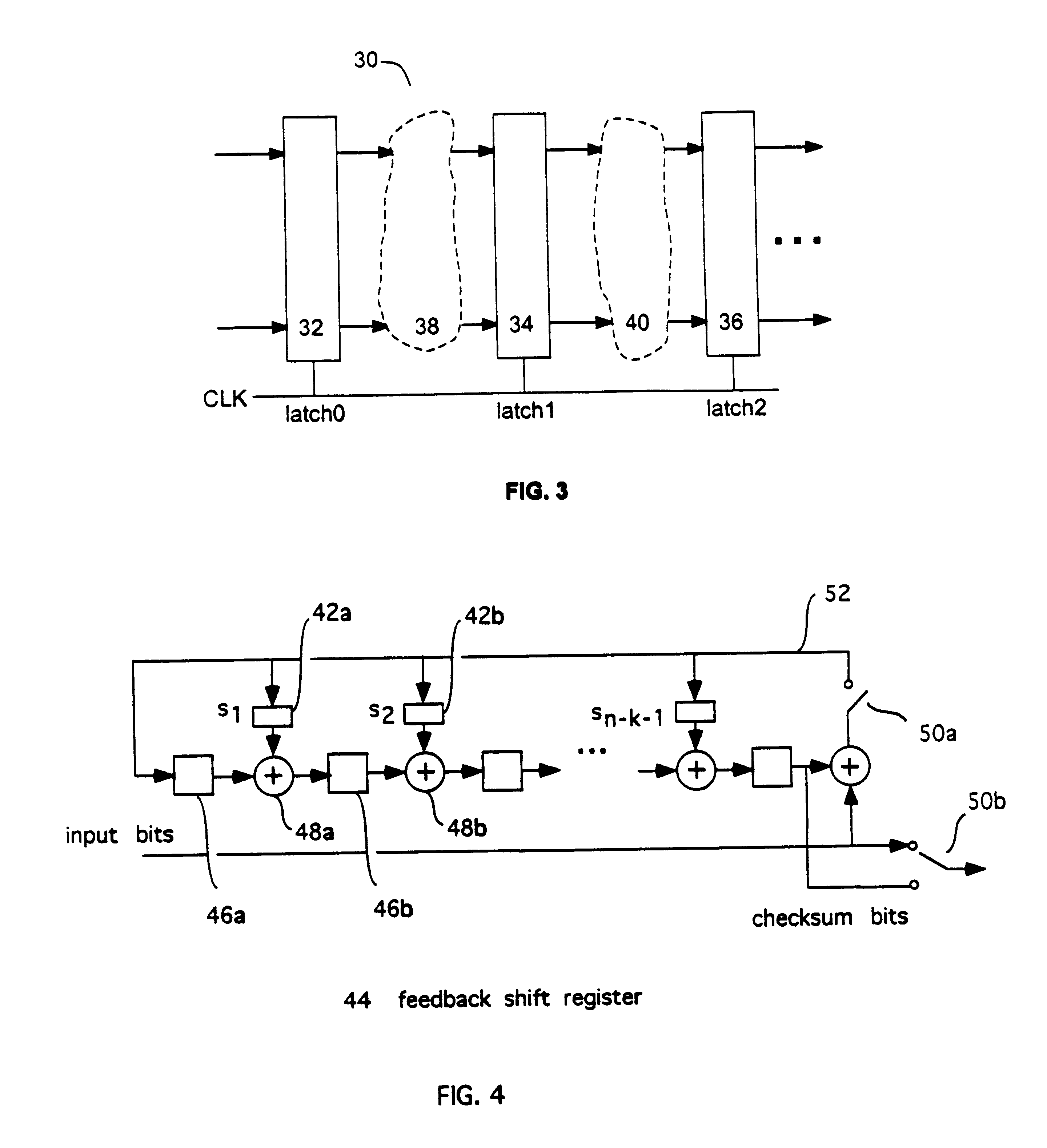
bit error rate (BER), includes encoding the data using a pipelineable BCH
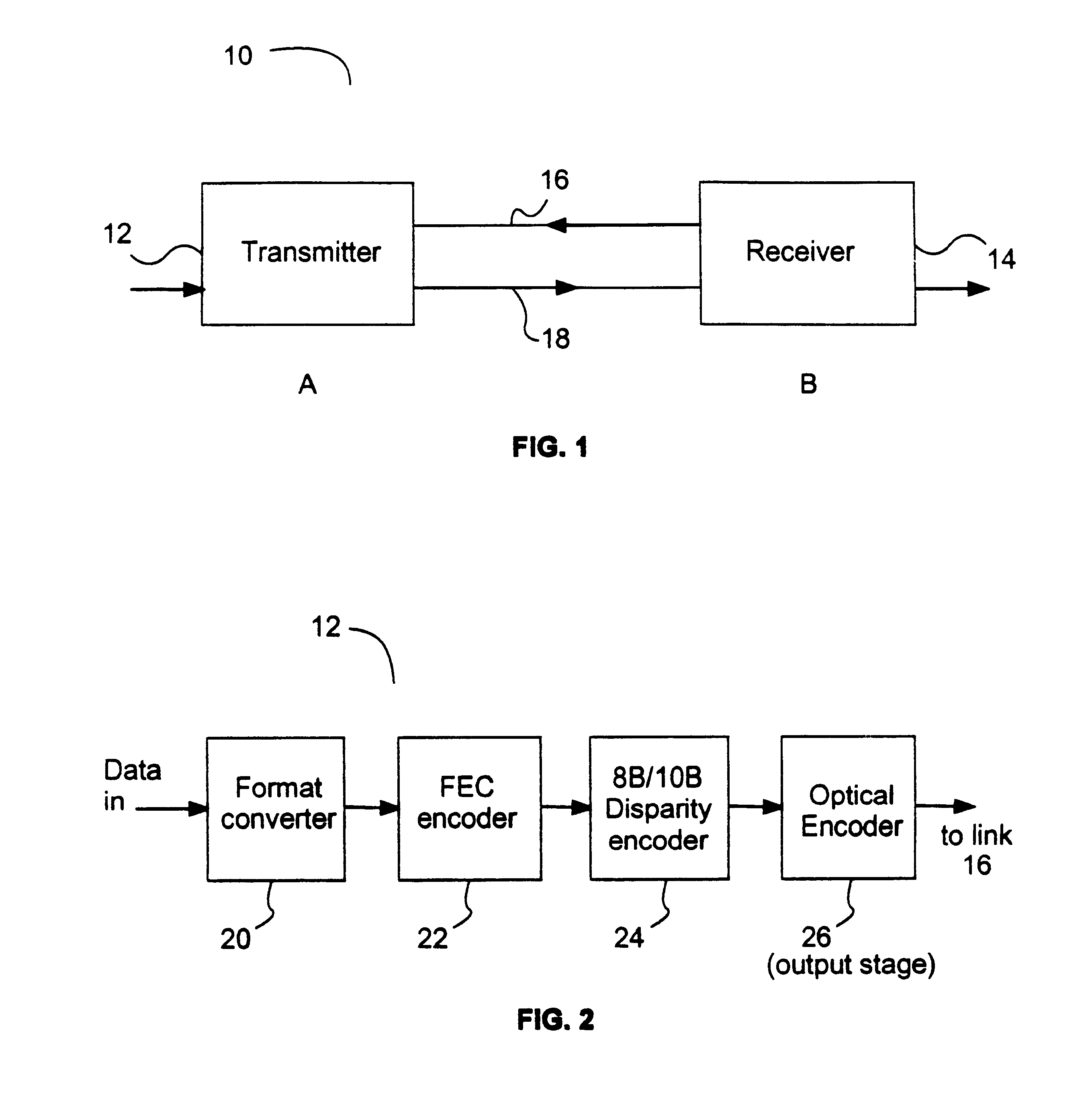
forward error correction (FEC) code. Forward error correctable data is transmitted within a bit
stream across the link at a speed that introduces errors at a rate that is in excess of the nominal BER but that allows for correction of errors so that the data may be received with less than the nominal BER.
[0025]In accordance with another aspect of the present invention, there is provided a
transmitter for transmitting data across a data link with a less than nominal bit error rate (BER). The transmitter includes a forward
error correcting (FEC)
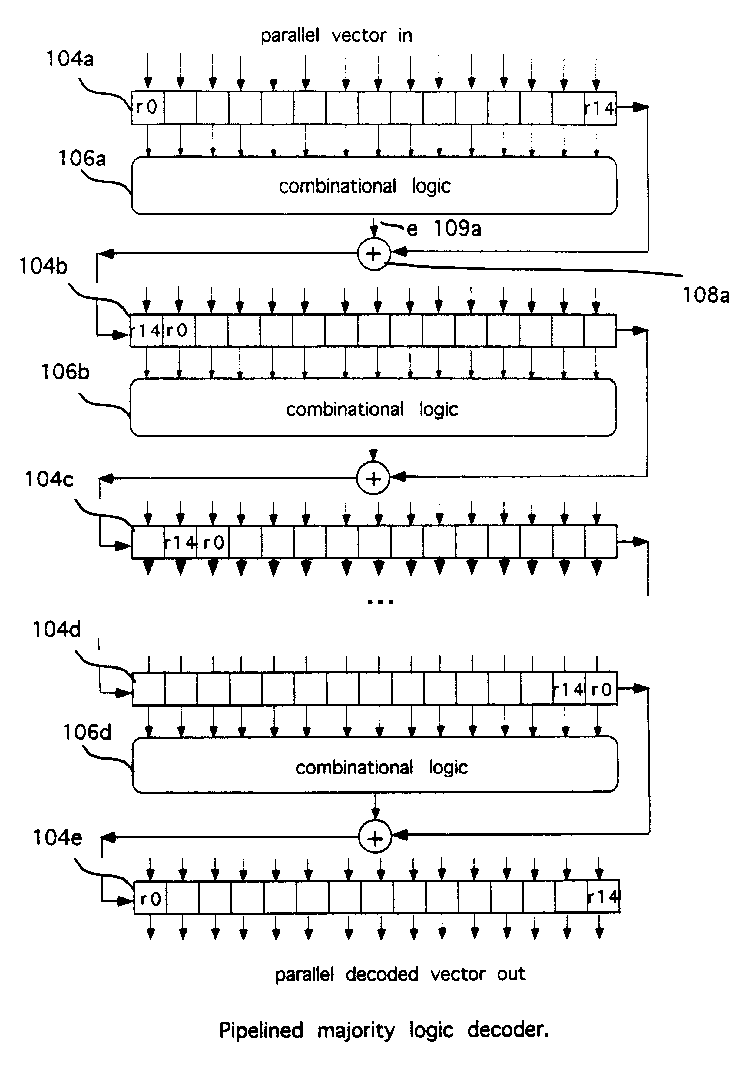
encoder for encoding the data using a pipelineable
majority logic decodable code to form forward error correctable data; and an output stage for outputting this data within a bit
stream across the link at a speed that introduces errors into the
stream at a rate that is in excess of the nominal BER but that allows for correction of errors within the data so that it may be received with less than the nominal BER.
[0029]In accordance with yet another aspect of the present invention, there is provided an optical
communications system comprising a transmitter; a
receiver and an
optical link communicatively
coupling the transmitter to the receiver. The transmitter, includes a forward
error correcting (FEC)
encoder for encoding data using a pipelineable BCH
error correcting code to form forward error correctable data; an output stage for outputting the forward error correctable data within a bit stream across the link. The output stage operates at a power and a speed in excess of a first nominal rate, so that errors are introduced in the stream and received at the receiver at a BER that is in excess of a nominal BER. The receiver includes a pipelined FEC decoder, operable to correct errors within the forward error correctable data from the receiver using the BCH error correcting code, so that the data may be received with less than the nominal BER, and at a
data rate above the first nominal rate. This increases the capacity of the
optical link at the operating power of the transmitter.
[0030]In accordance with another aspect of the present invention, there is provided an
optical transmitter including a buffer for buffering received data; a packet former for encoding data from the buffer into packets; an error detection (ED)
encoder adding error detection codes to the packets, an electrical to optical (E / O) generator in communication with the ED encoder to receive data from the ED encoder and produce at least one optical output
signal corresponding thereto for transmission across an
optical link and
receipt as at least one received optical
signal. The error detection codes allowing detection of at least one error in a packet. The optical generator operates at a
clock rate in excess of a nominal
clock rate, and at a
power level that causes errors to be introduced into the at least one received optical signals that are in excess of a first bit error rate (BER). A controller is in communication with the buffer to cause retransmission of the retransmission blocks within the buffer in response to retransmission requests, so that data may be received at a data rate in excess of the nominal
clock rate with less than a second BER.
[0031]An
optical transmitter comprising an input for receiving data to be transmitted, comprising a buffer for buffering received data; a packet former for encoding data from the buffer into packets, a plurality of error detection (ED) encoders adding error detection codes to the packets; at least one electrical to optical (E / O) generator in communication with the plurality of encoders to receive data from the encoders and produce at least one optical output
signal corresponding thereto for transmission across an optical link and
receipt as at least one received optical signal. The error detection codes allow detection of at least one error in a packet. The optical generator(s) operates at a nominal
clock rate and at a
power level that causes errors to be introduced into the received optical signal(s) that are in excess of a first bit error rate (BER). A controller is in communication with the buffer to cause retransmission of packets within the buffer in response to retransmission requests, so that data may be received with less than a second BER, at a data rate in excess of the nominal
clock rate.

