Exhaust emission control device

a technology of exhaust gas and control device, which is applied in the direction of electrical control, exhaust treatment electric control, separation process, etc., can solve the problems of increased pumping loss in the low rotation area, worse fuel consumption, and worse fuel consumption, so as to reduce the temperature of exhaust gas, prevent engine failure, and suppress output differences

Inactive Publication Date: 2005-02-08
MITSUBISHI MOTORS CORP
View PDF6 Cites 42 Cited by
  • Summary
  • Abstract
  • Description
  • Claims
  • Application Information

AI Technical Summary

Benefits of technology

The present invention has been achieved in the light of the above-mentioned problems, and it is an object of the invention to provide an exhaust emission control device useful for an engine with a turbo charger that is capable of suppressing an excessive rise in the exhaust gas temperature without making the fuel consumption worse and effectively preventing depression of the DPF holding alkaline metal catalyst.
Also, the exhaust gas passage has preferably oxidation catalyst disposed on the upstream side of the filter and on the downstream side of the turbine. Thereby, the particulate is burnt and removed at the exhaust gas temperature due to catalytic action of oxidation catalyst, allowing for the continuous regeneration of the filter.

Problems solved by technology

However, the alkaline metal catalyst causes depression in a high temperature area owing to reconnection of alkaline metal and splashing by evaporation, whereby it is necessary to suppress an excessive rise in exhaust gas temperature while driving fast or driving at high load.
Therefore, if an internal pressure of cylinder of the engine is suppressed within a permissible limit, it is required that the injection timing of fuel is retarded, resulting in a problem that the fuel consumption is worse.
Also, a pumping loss in the low rotation area is increased, leading to a risk that the fuel consumption is also worse.

Method used


Image

  • Exhaust emission control device
  • Exhaust emission control device
  • Exhaust emission control device

Examples


Embodiment Construction

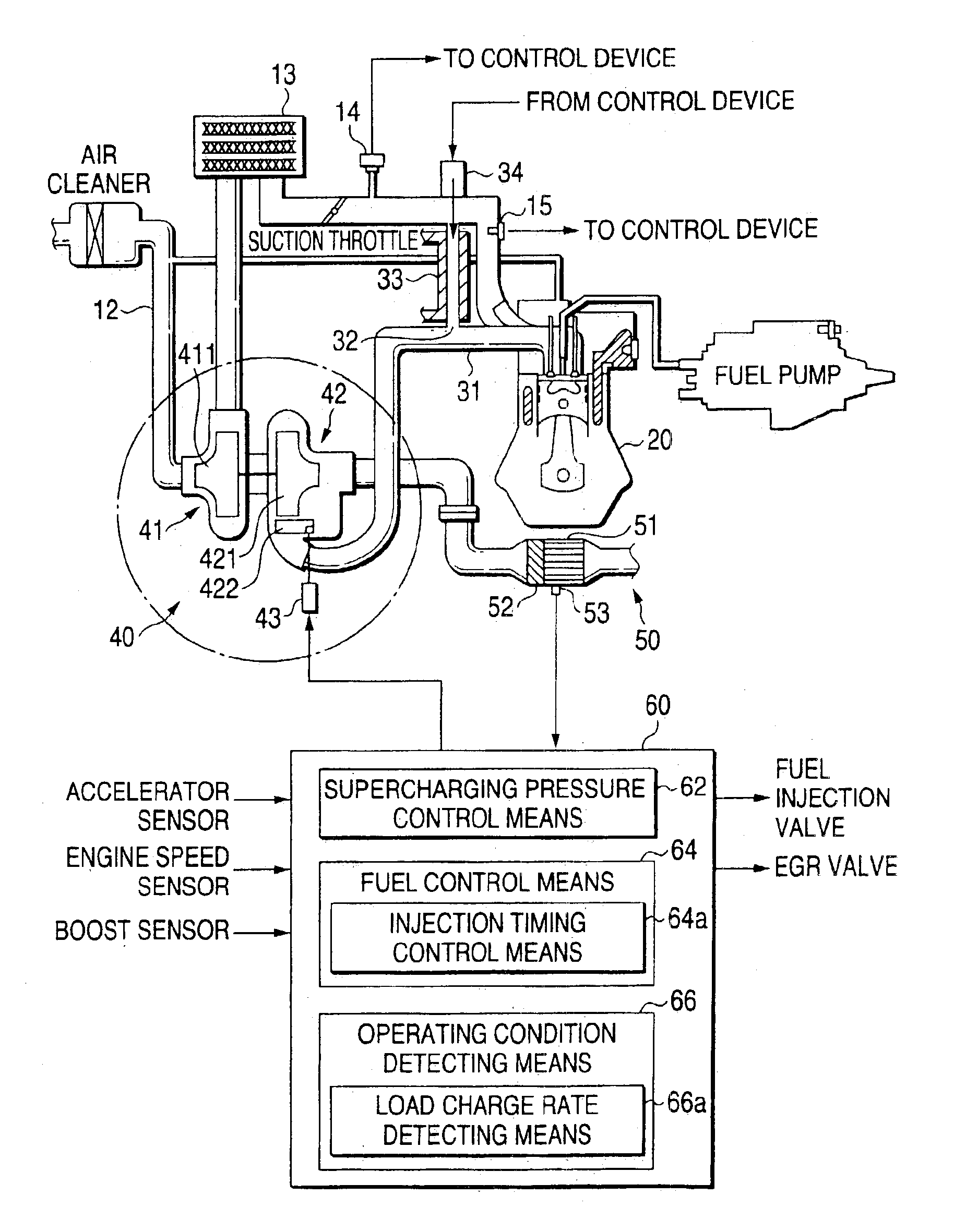
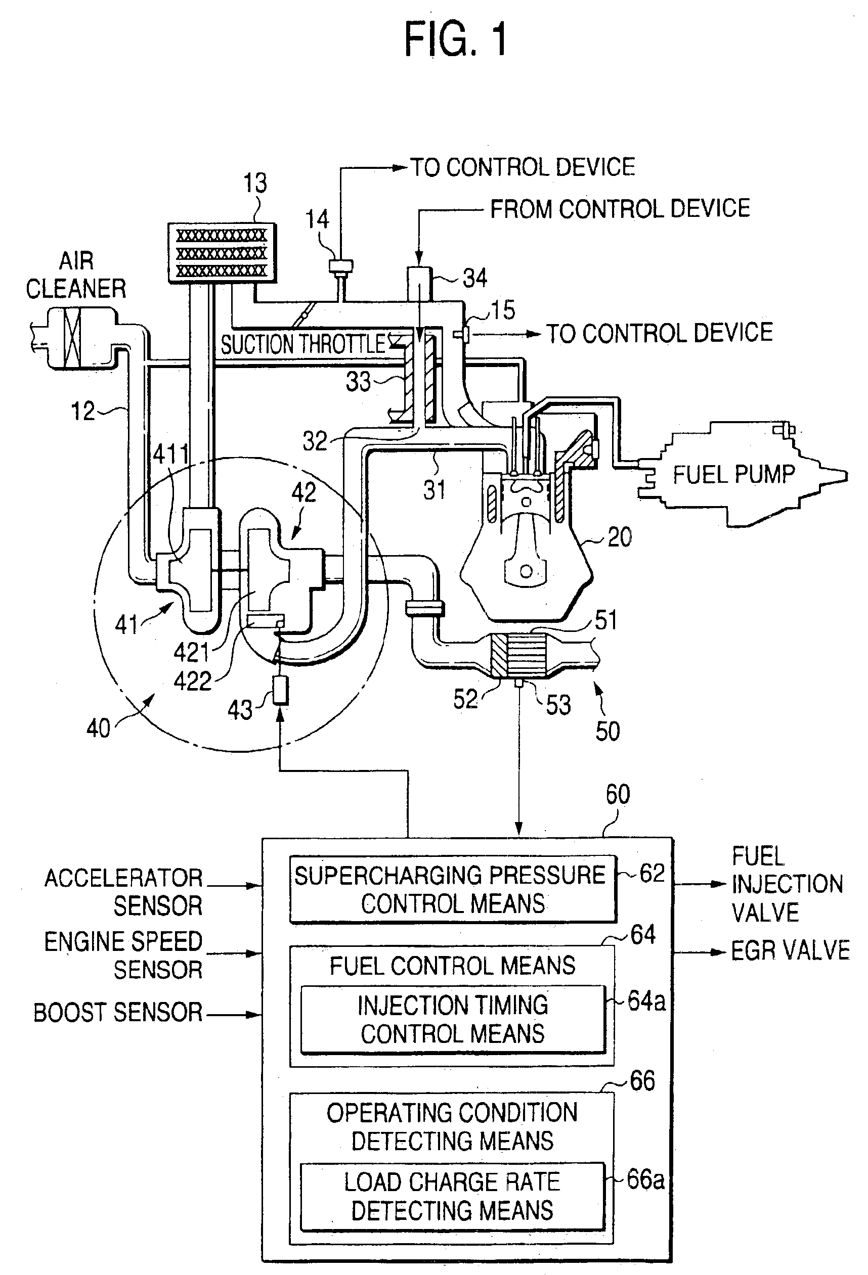
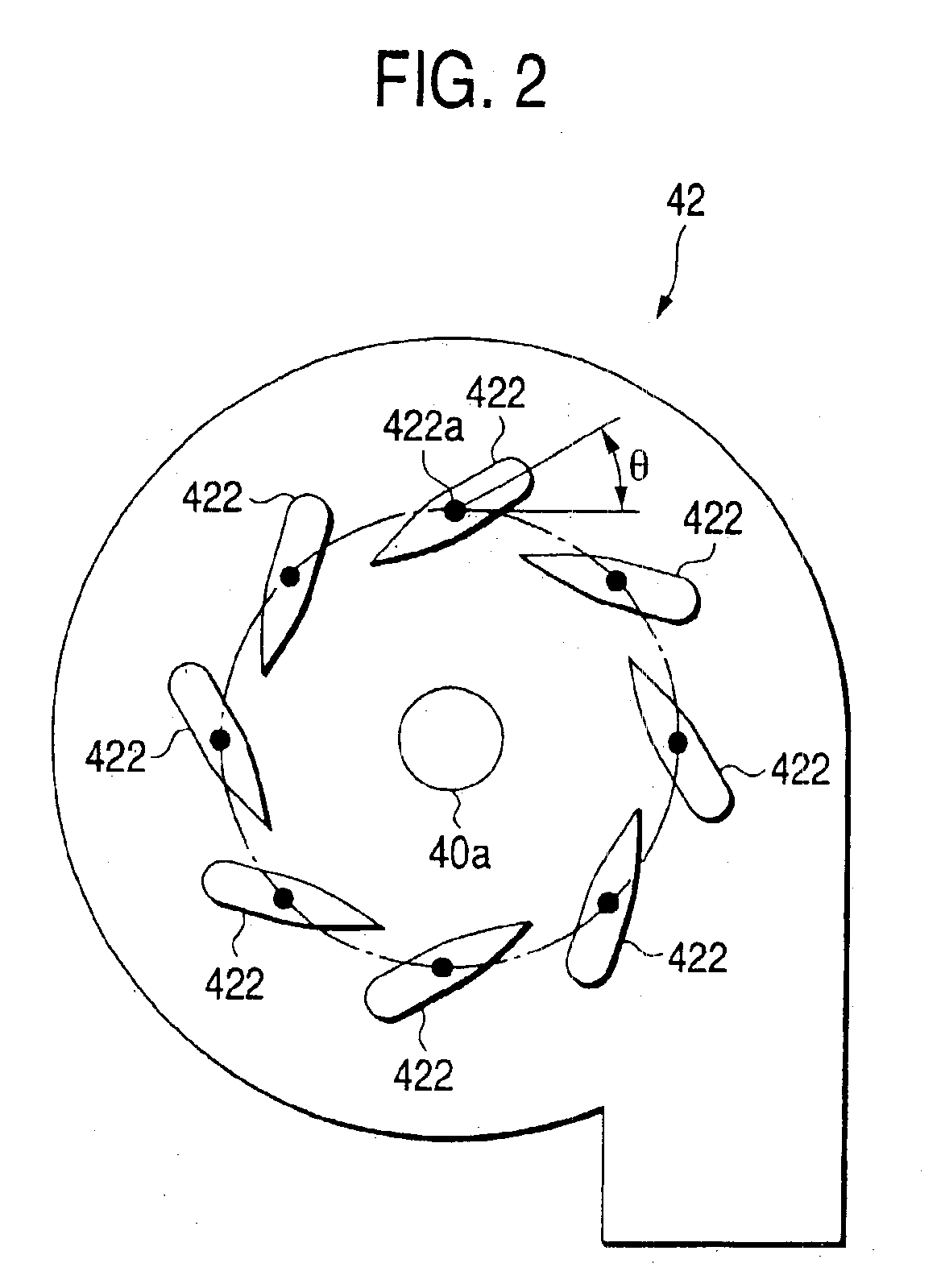
The preferred embodiments of an exhaust emission control device according to one embodiment of the present invention will be described below with reference to the accompanying drawings. FIG. 1 is a schematic view showing the overall constitution of a diesel engine equipped with this exhaust emission control device, FIGS. 2 and 3 are schematic views partially showing the exhaust emission control device, and FIG. 4 is a flowchart for explaining the action of the exhaust emission control device.

The diesel engine according to this embodiment comprises a turbo charger 40 having a compressor 41 and a turbine 42 that are integrally rotated by the same shaft 40a. The compressor 41 is interposed in a suction passage 12 on the inlet side of an engine main body 20 and the turbine 42 is interposed in an exhaust passage 31 on the outlet side of the engine main body 20. A soot removal device 50 for removing the soot is disposed in the exhaust gas in the exhaust passage 31 on the downstream side o...


PUM


Abstract

An exhaust emission control device has operating condition detecting means for detecting an operating condition of an engine, fuel control means for controlling fuel supply into a combustion chamber of the engine on the basis of an output of the operating condition detecting means, a turbo charger for supercharging a suction air with an exhaust gas of the engine, wherein a filter for capturing particulates in the exhaust gas is disposed in an exhaust gas passage on the downstream side of a turbine of the turbo charger, and the filter holds alkaline metal catalyst. Exhaust gas temperature sensing means senses (or estimates) the exhaust gas temperature near the filter, and supercharging pressure control means controls a supercharging pressure of the turbo charger to be increased when the exhaust gas temperature exceeds a predetermined temperature.

Description

BACKGROUND OF THE INVENTION1. Field of the InventionThe present invention relates to an exhaust emission control device suitably used for a diesel engine.2. Description of the Related ArtAn exhaust gas from the diesel engine contains the particulate (hereinafter referred to as soot) mainly composed of carbon. Various techniques for suppressing the soot to be exhausted into the atmosphere have been put into practical use.As one of the techniques, a continuous regeneration exhaust emission control device is well known in which an oxidation catalyst and a particulate capturing filter (abbreviated as DPF) are disposed in the order from the upstream side. Another device is also well known in which alkaline metal catalyst is held in the DPF to improve the regeneration performance of the DPF.However, the alkaline metal catalyst causes depression in a high temperature area owing to reconnection of alkaline metal and splashing by evaporation, whereby it is necessary to suppress an excessive ...

Claims


Application Information

Patent Timeline
Patent Type & Authority Patents(United States)
IPC IPC(8): B01D53/94F01N3/023F02D41/00F01N9/00F02M25/07F02D41/34F02D41/02F02B37/18F02B37/24F02M31/00F02B37/12F02M31/20F01N3/02F02B37/22F02D23/00F02D23/02F02D43/00
CPCB01D53/9495F01N3/0231F01N3/0236F01N9/002F01N9/005F02D41/0007F02D41/34F02M25/0724F02M25/0738F01N3/023Y02T10/47F01N2430/08F01N2510/06F01N2560/06F02B37/18F02B37/24F02D41/029F02D41/1446F02M25/0707F02M25/0713F02M25/0727F02M25/0772F02M31/20Y02T10/44Y02T10/144F02M26/05F02M26/10F02M26/21F02M26/23F02M26/33F02M26/53Y02T10/12Y02T10/40F02D43/00
Inventor CHAMOTO, TETSUOTERADA, MIKIO
Owner MITSUBISHI MOTORS CORP
Why Eureka
Try Eureka