System for exhaust/crankcase gas recirculation

a technology of exhaust gas recirculation and crankcase, which is applied in the direction of machines/engines, mechanical equipment, non-fuel substance addition to fuel, etc., can solve the problems of poor transient response performance of internal combustion engines, requiring a pumping arrangement or venturi arrangement, and increasing complexity and penalty in fuel consumption. , to achieve the effect of reducing pressure, reducing pressure, and high intake air velocity

Inactive Publication Date: 2005-02-08
MAHAKUL BUDHADEB
View PDF15 Cites 15 Cited by
  • Summary
  • Abstract
  • Description
  • Claims
  • Application Information

AI Technical Summary

Benefits of technology

The present invention defines a unique exhaust gas recirculation(EGR) / Crankcase gas recirculation arrangement. EGR / Crankcase gas is admitted into the engine with modifications in the cylinder head air inlet ports. Air flows into the cylinder as the intake valves open. The air induction stroke results in high velocity of the Intake air around the valve seat region due to the pressure gradient between the ports and the cylinder (FIG. 1). This increase in velocity leads to a region of low pressure. Introducing the exhaust gas from the exhaust manifold directly into the valve seat region will cause the exhaust to be drawn into the cylinder (FIG. 2). This arrangement may be utilized for drawing in crankcase ventilation gas also. A simulation was performed with a Computational fluid dynamics package to confirm this claim. The results of the simulation show the pressure distribution around the valve seat area of the inlet port (FIG. 1). It is clearly shown that the pressure in the valve seat region is significantly lower than the air supply pressure to the ports. For this case, the simulation started just prior to intake valve opening. At that crank angle, pressures and temperatures throughout the flow domain were uniform. Pressures and temperatures at the port ends were also equal. The figures show the pressure field at 80 degrees after-top-dead-center. This crank angle was chosen because the piston is moving fast then, resulting in large velocities in the valve curtain region, which give the lower pressures seen in the figure. At light load engine operation when the boost pressure is significantly low, the air induction process in the cylinder will draw in the exhaust gas into the cylinder. This system will ensure that EGR is supplied into the engine cylinder under all operating conditions. A pumping arrangement may be utilized to further enahnce the quatities of EGR / crankcase gas into the air intake port of an internal combustion engine. An actuator that will control the amount of flow into the cylinder shall provide the control of the exhaust into the cylinder. The actuator may be operated by a mechanical / hydraulic / pneumatic / electrical system. A simple design is shown in FIG. 3, which comprises of a pipe from the exhaust that is fed into a cooler. The amount of exhaust gas flow into the cylinder is controlled by the actuator that feeds into the individual cylinders. The exhaust gas flows into the cylinder only when the intake valves are open. The ability to supply exhaust gas, during the intake process, will result in minimal exhaust gas present in the intake port. This significantly improves transient response compared to other systems. Also due to the small quantities of exhaust gas being circulated in the system, the amount of exhaust gas cooling required will be minimal. The arrangement for crankcase gas is shown in FIG. 4. The crankcase gas is directly fed into the intake valve seat region as shown. The ability to introduce the crankcase gas back into the cylinder will result in significant reduction in particulate without causing any deterioration to engine performance.

Problems solved by technology

The difficulty in introducing EGR in internal combustion engines is that it requires a pumping arrangement or a venturi arrangement.
This adds complexity and penalty in fuel consumption.
In addition, filling up the air intake system with EGR often leads to poor transient response performance for an internal combustion engine.
A similar problem exists for crankcase breathing arrangements for internal combustion engines.
Venting crankcase gas into the exhaust causes an increase in Particulate matter and Hydrocarbon emission.
Also introducing the crankcase gases ahead of the turbocharger causes significant issues with fouling of the compressor and aftercoolers.
This results in loss of fuel economy.
However at part load the supply of EGR is limited.
This system requires throttling of the Intake runners and complicated valve arrangement for part load EGR delivery.
Throttling of the Intake air results in fuel consumption loss and potential for increase in particulate.
Both these features will result in fuel consumption loss and in a complicated system.

Method used


Image

  • System for exhaust/crankcase gas recirculation
  • System for exhaust/crankcase gas recirculation
  • System for exhaust/crankcase gas recirculation

Examples


Embodiment Construction

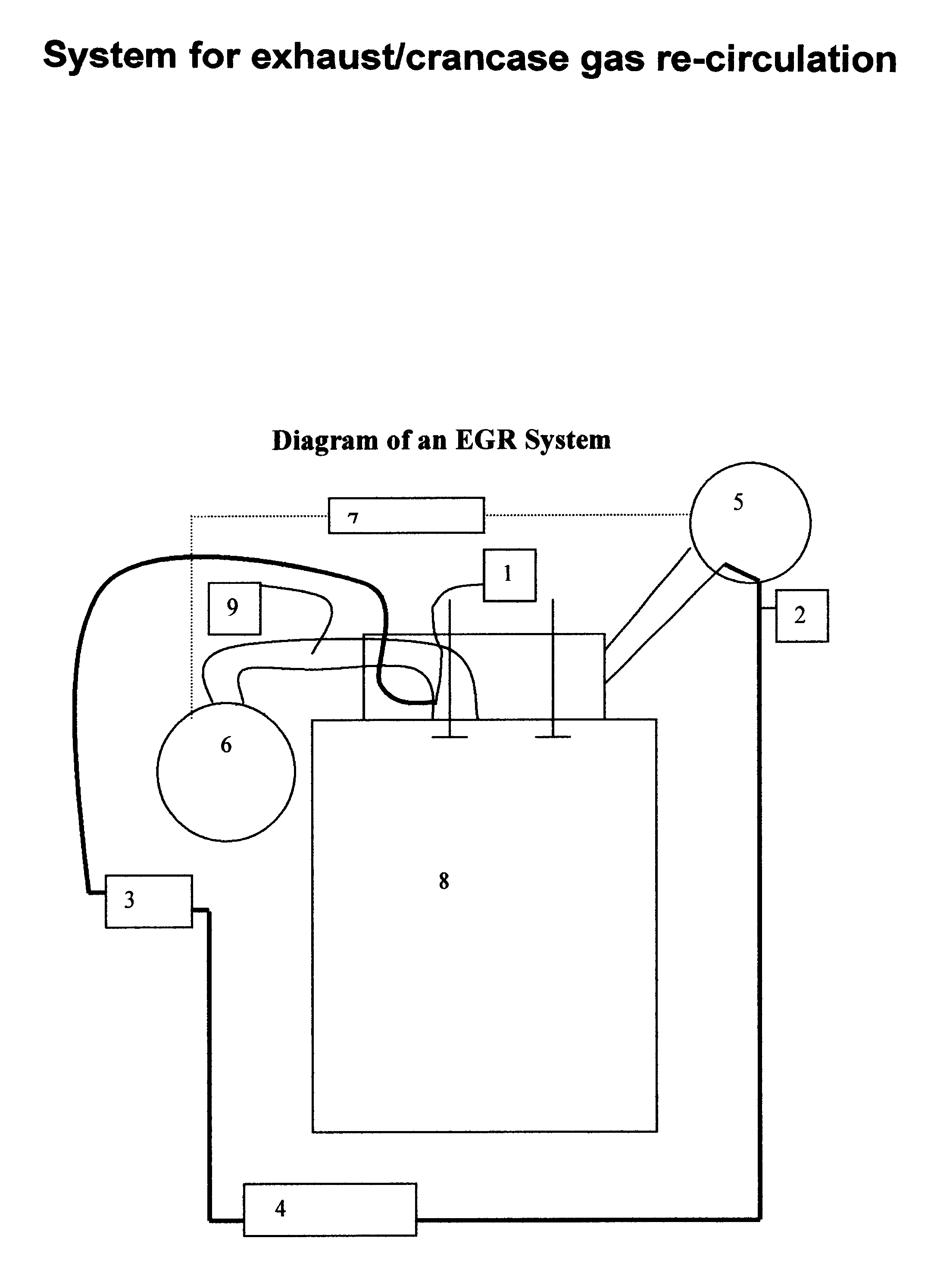
The present invention will be described hereinafter with reference to the preferred embodiments thereof in conjunction with the accompanying drawings. First referring to FIG. 3, indicated at 8 is an internal combustion engine; 9, an intake port and 5 and exhaust manifold. The intake port 9 and exhaust manifold 5 are connected to each other by means by means of a recirculation pipe 2, EGR cooler 4 and exhaust gas control valve 3. To introduce EGR into the system, exhaust gas is drawn from the system before the turbocharger 5 and led through the pipe 2 into an EGR cooler 4. From there the exhaust gas is fed through the control valve 3, which regulates the quantity of EGR into the intake port / s location 1.

The operation of the crankcase gas arrangement is shown in FIG. 4. Blowby gas 2 from the crankcase is directed into the oil separator 3. From there the crankcase gas is led to the intake port location 1 above the valve seat area. This will ensure a positive flow of crankcase into the ...


PUM


Abstract

An exhaust gas recirculation system for an internal combustion engine by which a portion of exhaust gas from the engine is recirculated from an exhaust line of the engine into an intake line of the engine, introducing the exhaust gas flow into the intake port around the intake valve seat region. The present invention provides a unique means of introducing EGR/Crankcase gas into the combustion chamber of an engine. The location for introducing EGR/Crankacse gas is above the intake valve seat region. The system does not require any pumping arrangement either through the use of external pumps or by raising the exhaust back presssure in the system. This system does not penalize airflow into the system as the flow passage does not require reduction in size to the air passage. Introducing the EGR just during the air induction process means the quantity of exhaust gas in the system is minimal. This results in improved transient response. Use of minimal EGR also results in smaller EGR cooling system. The introduction of crankcase into the combustion chamber results in lowering of the particulates in the exhuast. The oil particles in the crankcase gas also improves intake valve life.

Description

BACKGROUND1. Field of InventionThis invention relates to exhaust gas recirculation (EGR) or crankcase blowby gas recirculation system into an internal combustion engine. More specifically this invention relates to an exhaust gas recirculation system or crankcase blowby system to reduce NOx emission and Hydrocarbon / Particulate emission.2. Description of Prior ArtWith continued tightening of the emission standards for internal combustion engines, particularly NOx, not only has the need to recirculate exhaust gases back into the engine become important, but also has the need to improve EGR technology. The crankcase ventilation gases emit significant amount of particulate and hydrocarbon into the exhaust. Therefore, a means to develop a system to recirculate crankcase gas back into the engine intake system becomes important.Significant efforts in research and development have been undertaken to re-circulate exhaust gas into the engine. The reason for introducing EGR (exhaust gas re-circ...

Claims


Application Information

Patent Timeline
Patent Type & Authority Patents(United States)
IPC IPC(8): F02B25/06F02B25/00F02M25/07F02M25/06
CPCF02B25/06F02M25/06F02M25/0723Y02T10/121F02M25/0727F02M26/20F02M26/23Y02T10/12
Inventor MAHAKUL, BUDHADEBHESSEL, RANDY PAUL
Owner MAHAKUL BUDHADEB
Why Eureka
Try Eureka