
Method and apparatus for shaping semisolid metals

a semi-solid metal and metal technology, applied in the direction of metal founding, chemistry apparatus and processes, etc., can solve the problems of cumbersome method (a) and high production cost, and the above-described conventional method has its own problems

Inactive Publication Date: 2005-02-08
UBE IND LTD
View PDF26 Cites 15 Cited by
  • Summary
  • Abstract
  • Description
  • Claims
  • Application Information

AI Technical Summary

Benefits of technology

The present invention relates to a method for shaping semisolid metals by using a nucleus generating section to create crystal nucleation in a liquid alloy, followed by a crystal generating section where the alloy is maintained as it cools. The invention also includes an apparatus for producing semisolid forming metals with fine primary crystals dispersed in a liquid phase. The technical effects of the invention include improved shaping of semisolid metals through the use of crystal nucleation, reduced formation of coarse grain structures, and improved mechanical properties of the shaped metal.

Problems solved by technology

However, the above-described conventional methods have their own problems.
Method (A) is cumbersome and the production cost is high irrespective of whether the agitation or recrystallization technique is utilized.
When applied to magnesium alloys, method (B) is economically disadvantageous since Zr is an expensive element and concerning method (C), in order to ensure that carbonaceous refiners will exhibit their function to the fullest extent, the addition of Be as an oxidation control element has to be reduced to a level as low as about 7 ppm, but then the alloy is prone to burn by oxidation during the heat treatment just prior to molding and this is inconvenient in operations.
In the case of aluminum alloys, about 500 μm is the size that can be achieved by the mere addition of refiners and it is not easy to obtain crystal grains finer than 100 μm to 200 μm.
To solve this problem, increased amounts of refiners are added in method (D), but this is industrially difficult to implement because the added refiners are prone to settle on the bottom of the furnace; furthermore, the method is costly.
According to method (F), partially molten aluminum having spherical particles in the microstructure can be obtained conveniently but no conditions are available that provide for direct shaping.
Moreover, thixo-casting methods (A)-(F) have a common problem in that they are more costly than the existing casting methods because in order to perform molding in the semisolid state, the liquid phase must first be solidified to prepare a billet, which is heated again to a temperature range that produces a semisolid metal.
In addition, the billets as the starting material are difficult to recycle and the liquid fraction cannot be increased to a very high level because of handling considerations.
Specifically, if the casting machine fails, difficulty arises in the processing of the semisolid metal.
However, the desired rheo-casting semisolid metal which has a fraction liquid and a temperature profile that are suitable for shaping cannot be obtained by merely holding the cooled metal in the specified temperature range for a specified period.
In method (I), a case for cooling the metal in a vessel is employed but the top and the bottom portions of the metal in the vessel will cool faster than the center and it is difficult to produce a partially solidified billet having a uniform temperature profile and immediate shaping will yield a product of nonuniform structure.
Furthermore, considering the need to satisfy the requirement that the partially solidified billet as taken out of the billet case has such a temperature that the initial state of the billet is maintained, it is difficult for the liquid fraction of the partially solidified billet to exceed 50% and the maximum that can be attained practically is no more than about 40%, which makes it necessary to give special considerations in determining injection and other conditions for shaping by diecasting.
If the liquid fraction of the billet has dropped below 40%, it could be reheated with a r-f induction heater but is is still difficult to attain a liquid fraction in excess of 50% and special considerations must be made in injection and other shaping conditions.
In addition, eliminating any significant temperature uneveness that has occurred within the partially solidified billet is a time-consuming practice and it is required, although for only a short time, that the r-f induction heater produce a high power comparable to that required in thixo-casting.
Another problem with the industrial practice of shaping semisolid metals in a continuous manner is that if a trouble occurs in the casting machine, the semisolid metal may occasionally be held in a specified temperature range for a period longer than the prescribed time.
Unless a certain problem occurs in the metallographic structure, it is desired that the semisolid metal be maintained at a specified temperature; in practice, however, particularly in the thixo-casting process where the semisolid metal is held with its temperature elevated from room temperature, the metallographic structure becomes coarse and the billets are considerably deformed (progressively increase in diameter toward the bottom) and, in addition, such billets are usually discarded, which is simply a waste in resources, unless their temperatures are individually controlled.

Method used


Image

  • Method and apparatus for shaping semisolid metals
  • Method and apparatus for shaping semisolid metals
  • Method and apparatus for shaping semisolid metals

Examples


example 1

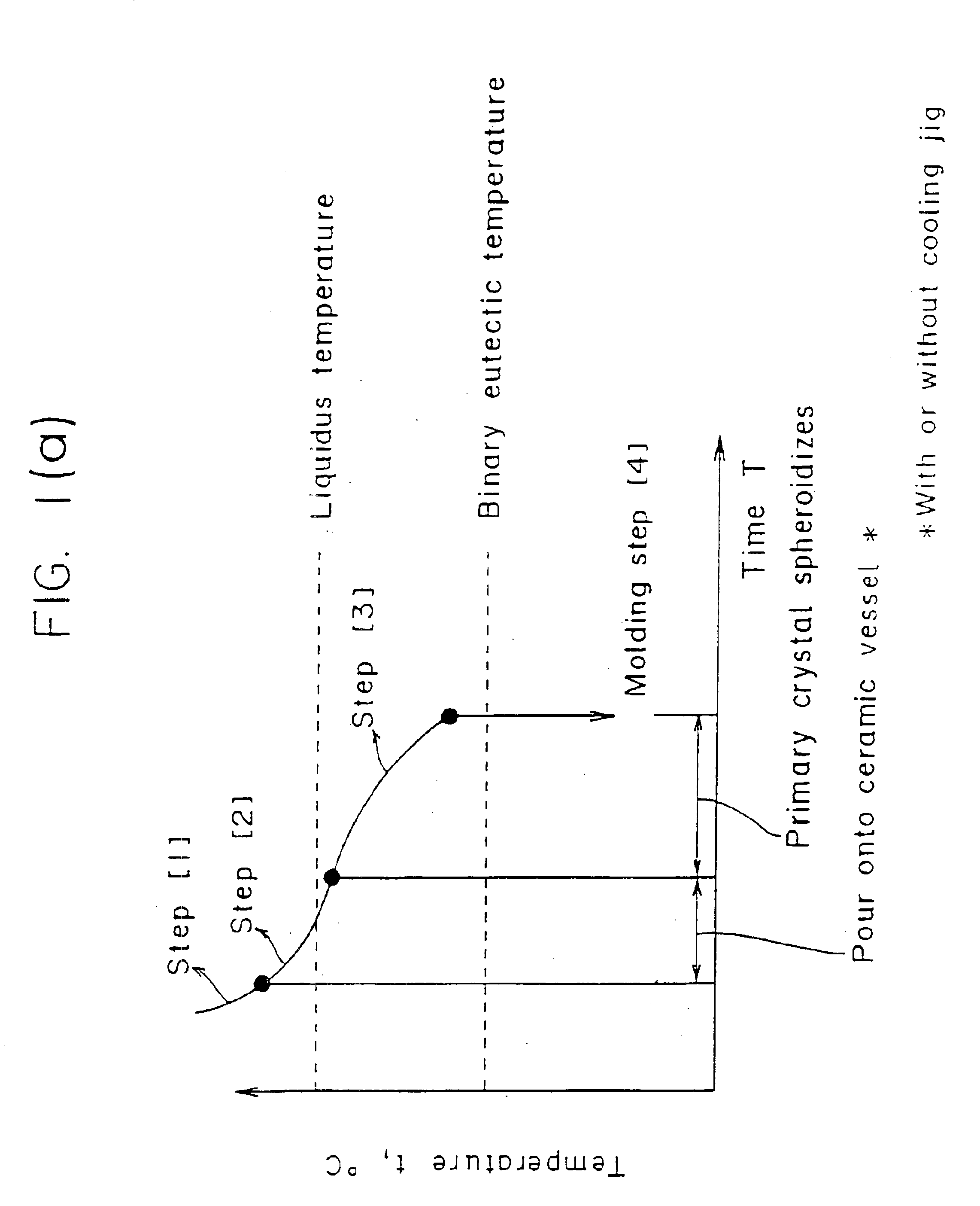
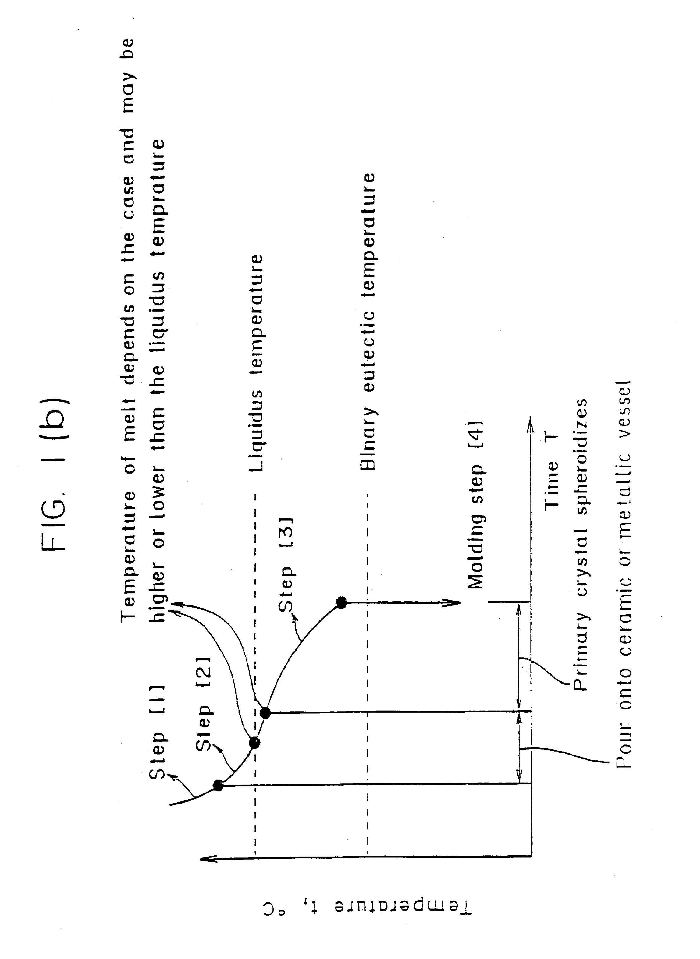
An example of the invention (as in the fifth to the tenth embodiments of the present invention) will now be described in detail with reference to accompanying FIGS. 1(a), 2(a), 3(a), 4, 5(a), 6(a), 7(a) and 8(a), in which: FIG. 1(a) is a diagram showing a process sequence for the semisolid forming of a hypoeutectic aluminum alloy having a composition at or above a maximum solubility limit; FIG. 2(a) is a diagram showing a process sequence for the semisolid forming of a magnesium or aluminum alloy having a composition within a maximum solubility limit; FIG. 3(a) shows a process flow starting with the generation of spherical primary crystals and ending with the molding step; FIG. 4 shows diagrammatically the metallographic structures obtained in the respective steps shown in FIG. 3(a); FIG. 5(a) is an equilibrium phase diagram for an Al—Si alloy as a typical aluminum alloy system; FIG. 6(a) is an equilibrium phase diagram for a Mg—Al alloy as a typical magnesium alloy system; FIG. 7(a...

example 2

An example of the invention (as in the eleventh to the thirteenth embodiments of the present invention) will now be described in detail with reference to accompanying drawings. As shown in FIGS. 9-12, the eleventh to thirteenth embodiments of the present invention is such that:(1) the melt of a hypoeutectic aluminum alloy of a composition at or above a maximum solubility limit or a magnesium or aluminum alloy of a composition within a maximum solubility limit which are held superheated less than 300° C. above the liquidus temperature is contacted with a surface of a jig having a lower temperature than the melting point of the alloy so as to generate crystal nuclei in the alloy solution which is then poured into an insulated vessel; or(2) the melt of an aluminum or magnesium alloy that is held superheated to less than 100° C. above the liquidus temperature is directly poured into an insulated vessel without using any jig, thereby generating crystal nuclei in the liquid alloy.

Subseque...

example 3

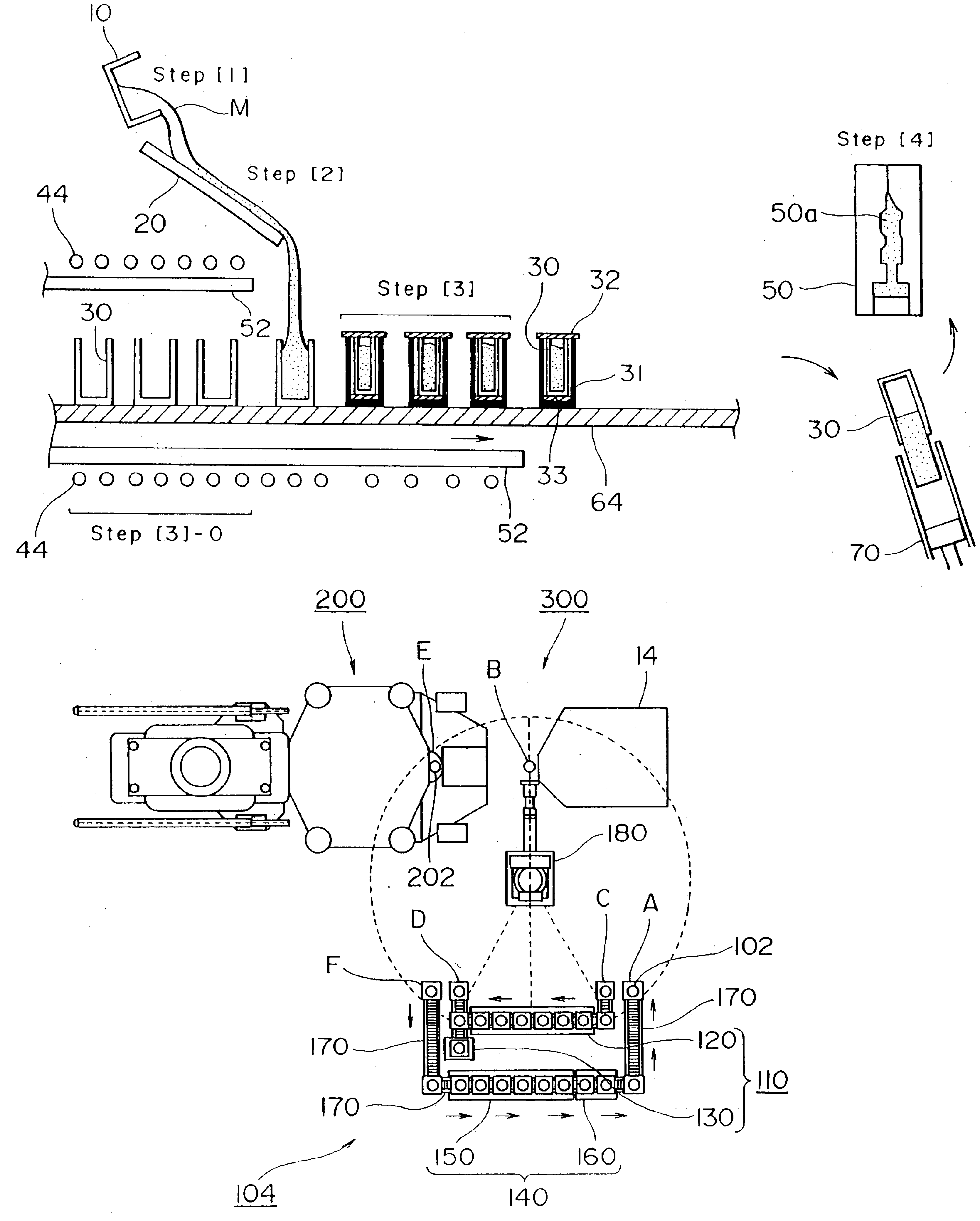
An example of the invention (as in the fourteenth to fifteenth embodiments of the present invention) will now be described in detail with reference to the accompanying FIGS. 3(a), 7(a), 8(a) and 2128, in which: FIG. 21 is a side view of an apparatus 100 for producing a semisolid forming metal; FIG. 22 is a perspective view of a cooling jig 1 as part of the nucleus generating section 12 of the apparatus 100; FIG. 23 shows in cross section two other cooling jigs 1A and 1B; FIG. 24 is a sectional side view of another cooling jig 1C which is funnel-shaped; FIG. 25 is a plan view showing the general layout of another apparatus 100A for producing a semisolid forming metal; FIG. 26 is a longitudinal section A—A of FIG. 25; FIG. 27 is a longitudinal section B—B of FIG. 25; FIG. 28 is a longitudinal section of an insulated vessel 22; FIG. 3 shows a process flow illustrating the method of producing a semisolid forming metal; FIG. 7 is a diagrammatic representation of a micrograph showing the ...


PUM

PropertyMeasurementUnit
liquidus temperatureaaaaaaaaaa
thermal conductivityaaaaaaaaaa
temperatureaaaaaaaaaa

Abstract

A method of shaping a semisolid metal to provide shaped parts which are produced in a convenient, easy and inexpensive manner, without relying upon the conventional mechanical or electromagnetic agitation. The method includes feeding, without using a cooling jig, into an insulating vessel, a molten alloy containing an element for promoting generation of crystal nuclei and being held to be superheated to less than 100° C. above a liquidus temperature of the alloy; maintaining the molten alloy in the insulating vessel for 5 seconds to 60 minutes as the alloy is cooled at a cooling rate of 0.01° C. / s to 3.0° C. / s thereby crystallizing fine primary spherical crystals in an alloy solution containing a specified liquid fraction; and feeding the alloy solution into a forming mold for shaping the alloy under pressure.

Description

BACKGROUND OF THE INVENTIONFIELD OF THE INVENTIONThis invention relates to a method of shaping semisolid metals. More particularly, the invention relates to a method of shaping semisolid metals, in which a liquid alloy having crystal nuclei at a temperature not lower than the liquidus temperature or a partially solid, partially liquid alloy having crystal nuclei at a temperature not lower than a molding temperature is fed into an insulated vessel having a heat insulating effect, holding the alloy for a period from 5 seconds to 60 minutes as it is cooled to the molding temperature where a specified liquid fraction is established, thereby generating fine primary crystals in the alloy solution and the alloy is shaped under pressure. The invention also relates to an apparatus for implementing this method.More particularly, the invention further relates to a method of shaping semisolid metals, in which a liquid alloy having crystal nuclei and at a temperature not lower than the liquidus ...

Claims


Application Information

Patent Timeline
Patent Type & Authority Patents(United States)
IPC IPC(8): B22D17/00C22C1/00
CPCB22D17/007C22C1/005Y10S164/90C22C1/12
Inventor ADACHI, MITSURUSASAKI, HIROTOHARADA, YASUNORISAKAMOTO, TATSUOSATO, SATORU
Owner UBE IND LTD
Learn More