Drive unit for wheel and assembly method for the same

a technology of drive unit and axle unit, which is applied in the direction of bearing unit rigid support, couplings, transportation and packaging, etc., can solve the problems of reducing the hardness of the section of this inner-ring raceway b>8/b>, unable to maintain the durability of the bearing unit, and unable to transmit large torque through these fitting cylindrical surfaces. , to achieve the effect of improving assembly work efficiency and preventing nois

Inactive Publication Date: 2005-02-08
NSK LTD
View PDF16 Cites 10 Cited by
  • Summary
  • Abstract
  • Description
  • Claims
  • Application Information

AI Technical Summary

Benefits of technology

An objective of the present invention is to provide a drive unit for wheel to do away with these problems by preventing noise from occurring due to relative displacement in the circumferential direction between the male and female spline sections, and improving the efficiency of assembly work.
Another objective of the present invention is to provide an axle unit for wheel drive to do away with these problems by preventing noise from occurring due to relative displacement in the circumferential direction between the male and female spline sections, and improving the efficiency of assembly work.

Problems solved by technology

In other words, it is necessary to transmit large torque for driving between the first element 4, which supports the wheel, and the second element 5, which is connected to the drive shaft, however, since the cylindrical surfaces of these elements 4, 5 fit together, it is not possible to transmit large torque through these fitting cylindrical surfaces.
However, when this weld section 17 is welded using build-up welding all the way around, the heat during welding causes the shape of the inner-ring raceway 8a, which is formed on the outer peripheral surface of the first element 4, to deform, and as a result the hardness of the section of this inner-ring raceway 8 decreases and it becomes impossible to sufficiently maintain the durability of the bearing unit which includes this inner-ring raceway 8a.
In the case of this construction for transmitting the torque by the spline connection, although there is not the problem that existed in the first example of prior construction shown in FIG. 6, the specifications of the spline connection section must be accurately regulated, otherwise installation of this spline connection would become troublesome and abnormal noise could occur during operation which would give discomfort to the passengers of the vehicle.
In other words, when making the fit between the female spline section and male spline section of the spline connection by way of interference fit, the work of fitting these spline sections together becomes troublesome, large assembly equipment is necessary and efficiency of the assembly work is decreased.
On the other hand, when there is an excessively loose fit between the female spline section and male spline section, there is a large clearance between the side surfaces in the circumferential direction of the spline teeth of both of these spline sections, so during acceleration or deceleration, these side surfaces in the circumferential direction hit each other with large momentum and may cause noise that could cause discomfort to the passengers of the vehicle.

Method used


Image

  • Drive unit for wheel and assembly method for the same
  • Drive unit for wheel and assembly method for the same
  • Drive unit for wheel and assembly method for the same

Examples


first embodiment

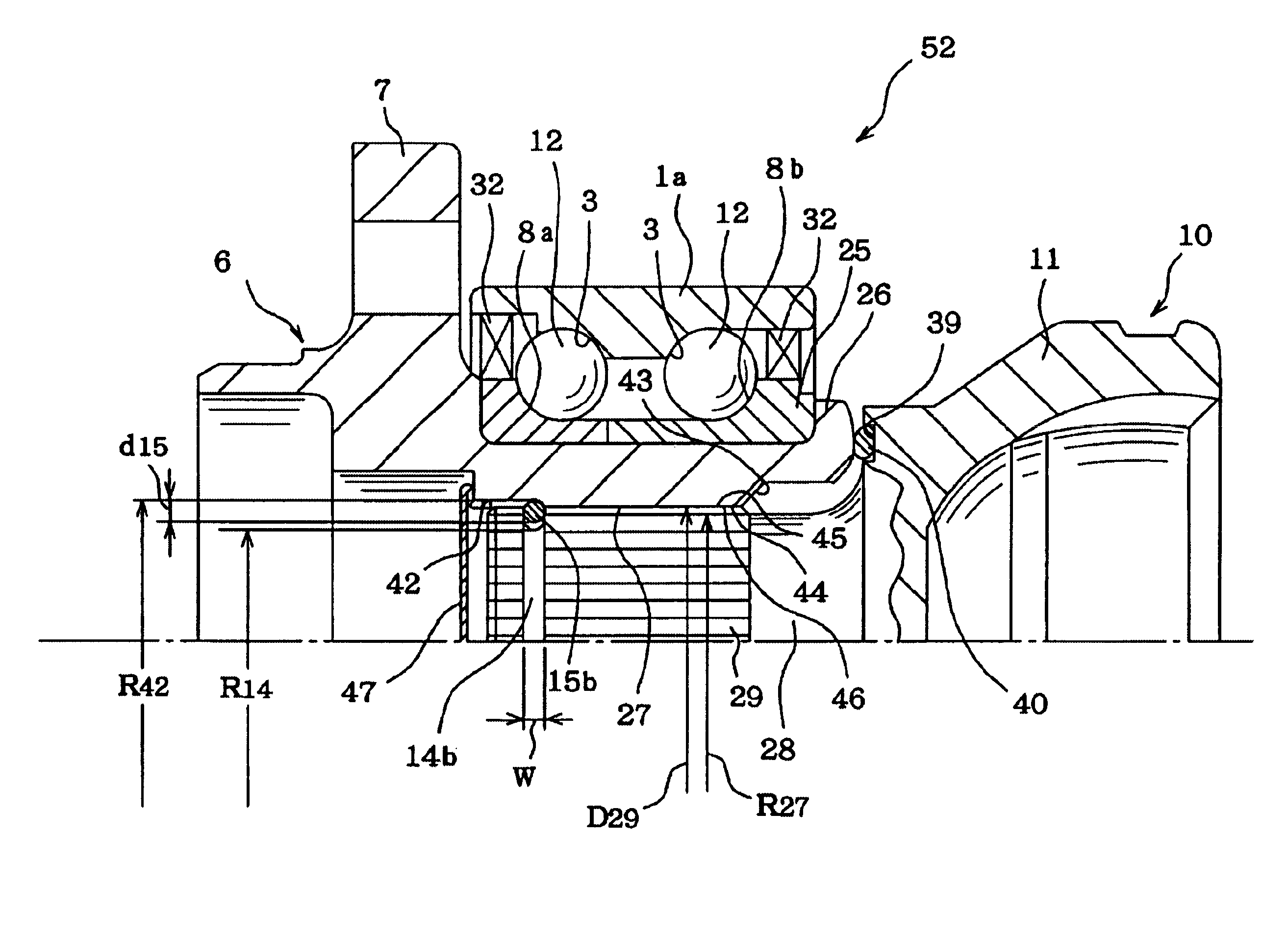
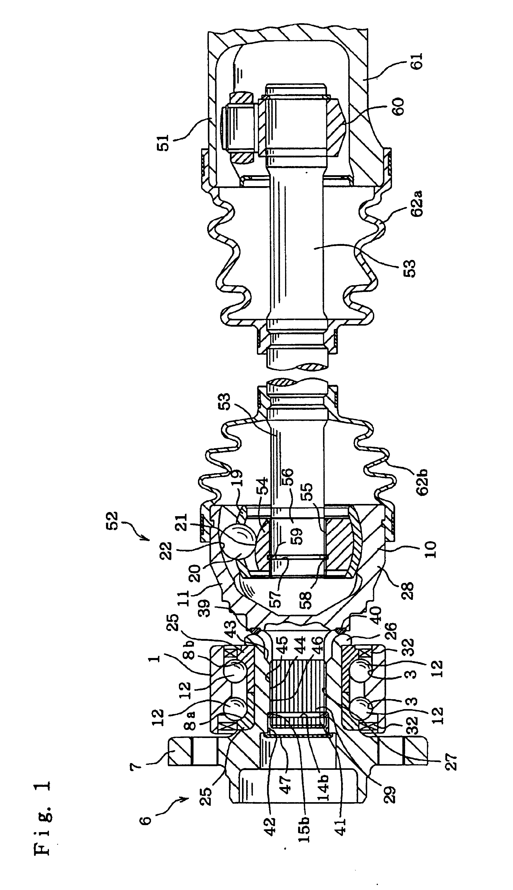
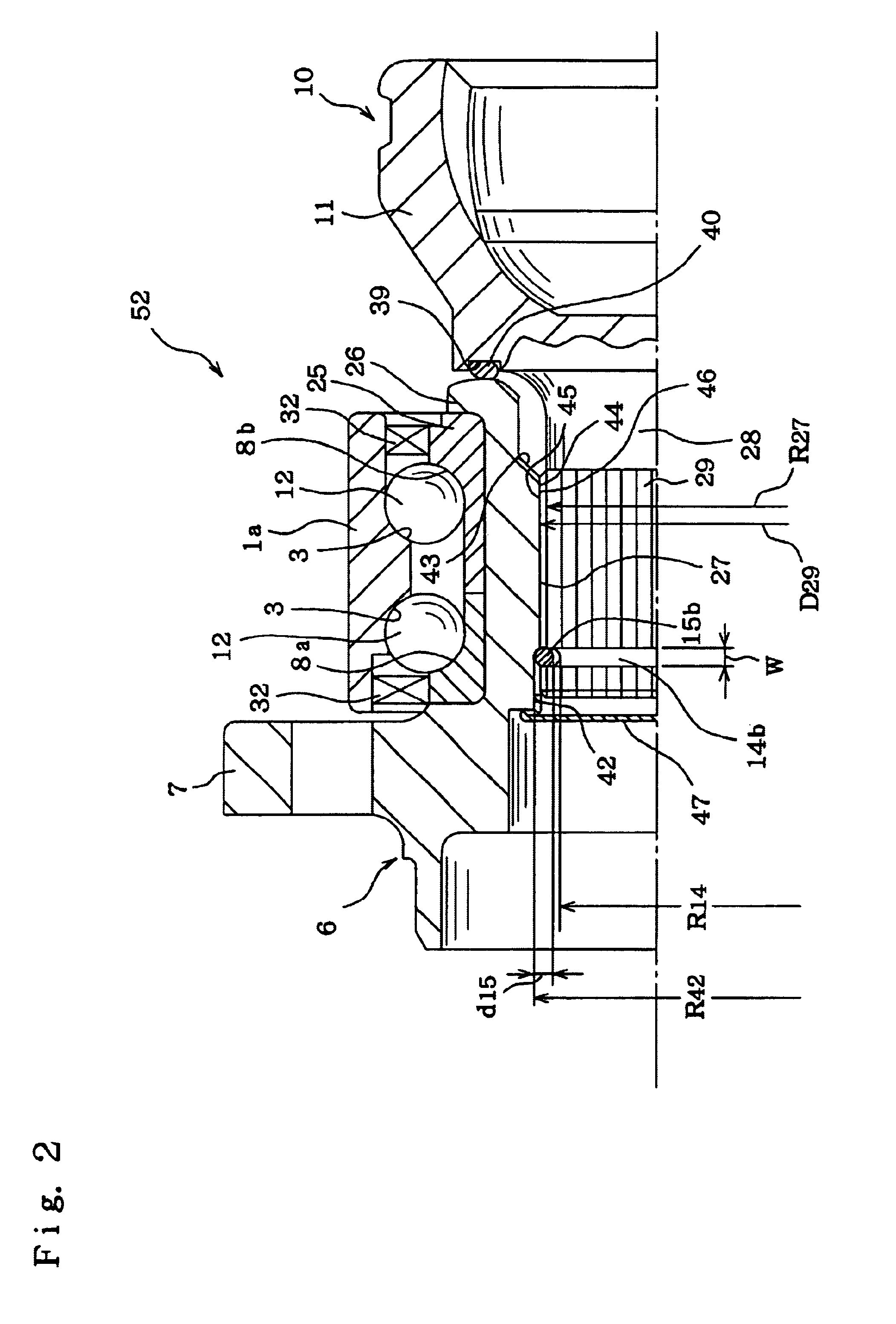
FIG. 1 and FIG. 2 show this invention. As shown in FIG. 1, the drive unit for wheel of this invention comprises a constant-velocity joint 51 on the differential side which can be referred to as the first constant-velocity joint, a bearing unit or axle unit 52 for driving a wheel, and a transmission shaft 53. This bearing unit or axle unit 52 for driving the wheel comprises a constant-velocity joint 10 on the bearing side which can be referred to as the second constant-velocity joint.

The constant-velocity joint 10 on the bearing side, the constant-velocity joint 51 on the differential side, and the transmission shaft 53 form a constant-velocity joint unit. In the case of this embodiment, the bearing unit 52 for driving the wheel is similar to that in the second example of prior construction shown in FIG. 7, in that the outer peripheral surface of the outer race 1 is formed in a simple cylindrical shape, and when fastened to the suspension, the outer race 1 fits inside an installation...

second embodiment

Next, FIG. 3 shows the invention. Similar to the third example of prior construction shown in FIG. 8, in this embodiment, the outside inner-ring raceway 8a is formed directly on the outer peripheral surface in the middle of the hub 6, and the inside inner-ring raceway 8b is formed around the outer peripheral surface of an inner race 25 that fits around a small-diameter stepped section 31 that is formed around the outer peripheral surface on the inside end of the hub 6, and the surface on the inside end of this inner race 25 is held by a crimped section 26.

Also, in this embodiment, there is a ring shaped metal core piece 49 having an L-shaped cross section and comprising an encoder 48 located in the middle of the drive member 28, that is the outside end of the housing section 11 so as to detect the rpm of the drive member 28.

Also, a ring-shaped elastic plate 50 that is attached to the outside surface of this metal core piece 49 is held between the surface on the outside end of the ho...

third embodiment

Next, FIG. 4 shows the invention. In this embodiment, a fitting groove 63 is formed on the outer peripheral surface of the housing section 11 of the drive member 28 of the constant-velocity joint 10 on the bearing side, and fitting protrusions 64 are formed on the outer peripheral surface in the middle of the transmission shaft 53. This fitting groove 63 and fitting protrusions 64, are formed so that when an assembly robot is used to insert the spline shaft 29 that is formed on the outside end of the drive member 28 into the spline hole 27 that is formed in the center of the hub 6, the robot arm is engaged with the groove 63 and protrusions 64 so that there is no slippage between the robot arm and the housing section 11 and transmission shaft 53.

Instead of the fitting groove 63 and fitting protrusions 64, it is also possible to form a minute land and recess section using knurling processing on part of the outer peripheral surface of the housing section 11 and transmission shaft 53 f...


PUM


Abstract

A combination of a constant-velocity joint and an axle unit for wheel-drive which comprises an outer race having an outer-ring raceway and being not rotatable even during use, a hub having an installation flange for supporting the wheel near the outside end, a first spline section and an inner-ring raceway near the inside end facing the outer-ring raceway, a drive member having a second spline section facing the first spline section, and a housing section forming an outer ring of the constant velocity joint, a plurality of rolling bodies between the outer-ring raceway and inner-ring raceway, the hub being engaged with the drive member by way of a spline connection with a pitch circle, and a coupling member adapted to freely deform elastically in the radial direction and located between and engaged with the first engagement section and the second engagement section so as to position the hub and drive member in the axial direction, wherein the clearance width in the circumferential direction on the pitch circle is controlled within the range of 0.001 mm to 0.10 mm.

Description

FIELD OF THE INVENTIONThe present invention relates to a drive unit for wheel or axle unit for wheel drive to rotatably support a wheel with respect to a suspension, and to transmit power that is output from a differential gear to the wheel.BACKGROUND OF THE INVENTIONThe drive unit for wheel comprises a rolling-bearing unit or hub unit for supporting the wheel, a constant-velocity joint unit and a coupling member, so as to support the drive wheel {front wheel for a FF vehicle (front engine, front-wheel-drive vehicle), rear wheel for a FR vehicle (front engine, rear-wheel-drive vehicle), and any wheel for a 4WD (four-wheel-drive vehicle)} that is supported by an independent suspension rotatably with respect to the suspension, whereby the drive unit for wheel drives and rotates the drive wheel.A hub unit or axle unit for wheel drive which can be connected and disconnected to a constant-velocity joint is called “fourth generation hub unit”.In order to support a wheel such that it can r...

Claims


Application Information

Patent Timeline
Patent Type & Authority Patents(United States)
IPC IPC(8): B60B27/00B60B35/14B60B35/18F16C19/18F16D1/06F16D3/20
CPCB60B27/00F16C35/063F16C19/184F16C2326/02F16D1/116F16D2001/103F16D2003/22326F16D3/223
Inventor KAYAMA, SHIGEOKIOUCHI, HIDEO
Owner NSK LTD
Why Eureka
Try Eureka