

Single phosphor for creating white light with high luminosity and high CRI in a UV LED device
a single phosphor, white light technology, applied in the direction of discharge tube luminescnet screen, x/gamma/cosmic radiation measurement, instruments, etc., can solve the problems of low efficiency of cerium doped yag, yellow color output, and undesired deviation from white in the color of the light generated by the system
Inactive Publication Date: 2005-02-08
GENERAL ELECTRIC CO
View PDF24 Cites 146 Cited by
- Summary
- Abstract
- Description
- Claims
- Application Information
AI Technical Summary
Benefits of technology
In view of the foregoing, it would be desirable to provide an illumination system that avoids or reduces the above mentioned problems.
Problems solved by technology
Third, the cerium doped YAG has a low efficiency and a yellow color output with excitation from a radiation source with wavelengths in the UV.
A deviation in cerium concentration from the desired concentration may result in an undesired deviation from white in the color of the light generated by the system.
Specifically, the cerium doped YAG phosphor system has a poor UV efficiency.
Furthermore, since blue radiation transmitted from the LED is required to produce white light, such white light output cannot be achieved using YAG-Ce3+ and a UV emitting LED.
This system requires more than a single phosphor to generate the white light illumination, and is complicated to manufacture.
Method used
View moreImage
Smart ImageViewing Examples

Examples
specific example
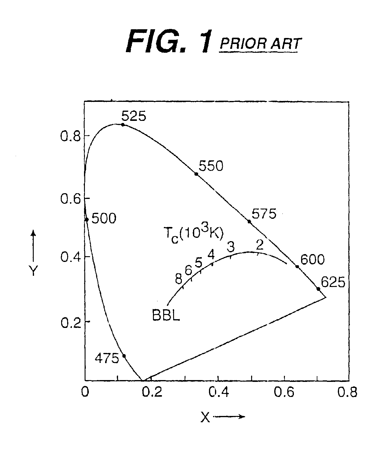
A Ca1.94Na1.03Eu0.03Mg2V3O12 phosphor was made by the following method. Stoichiometric amounts of oxide and carbonate starting materials (CaCO3, NaHCO3, NH4VO3, Eu2O3, and MgO) were ball milled for one hour. The resulting mixture was then fired at 800° C. in air for 10 hours to form Ca1.94Na1.03Eu0.03Mg2V3O12. The phosphor appeared white. The luminescence spectrum of the resulting phosphor is shown in FIG. 3 for 370 nm excitation. The chromaticity coordinates of the phosphor were (x=0.36, y=0.40) which corresponds to white light near the BBL with a CRI of 87 and a Tc=4670K. The phosphor had a luminosity of 354 lumens per watt.
Login to View More PUM
| Property | Measurement | Unit |
|---|---|---|
| CRI | aaaaa | aaaaa |
| color temperature | aaaaa | aaaaa |
| wavelengths | aaaaa | aaaaa |
Abstract
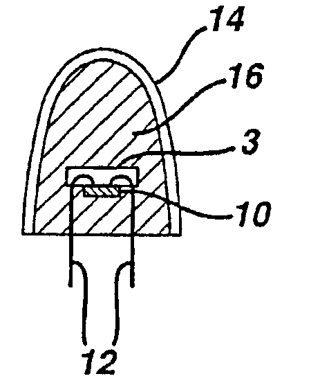
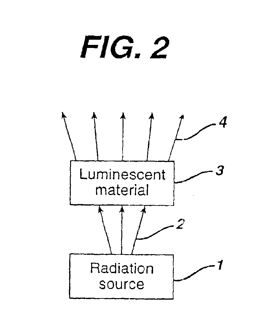
There is provided a white light illumination system. The illumination system includes a radiation source which emits either ultra-violet (UV) or x-ray radiation. The illumination system also includes a luminescent material which absorbs the UV or x-ray radiation and emits the white light. The luminescent material has composition A2−2xNa1+xExD2V3O12. A may be calcium, barium, strontium, or combinations of these three elements. E may be europium, dysprosium, samarium, thulium, or erbium, or combinations thereof. D may be magnesium or zinc, or combinations thereof. The value of x ranges from 0.01 to 0.3, inclusive.
Description
BACKGROUND OF THE INVENTIONThis invention relates generally to an illumination system which provides white light illumination. More particularly, it relates to an illumination system which provides illumination using an ultra-violet (UV) or x-ray radiation emitting device and a luminescent material which converts the UV radiation or x-rays to white light.A luminescent material absorbs energy in one region of the electromagnetic spectrum and emits radiation energy in another region of the spectrum. Typically, the energy of the photons emitted is lower than the energy of the photons absorbed. A luminescent material in powder form is commonly called a phosphor, while a luminescent material in the form of a transparent solid body is commonly called a scintillator.Most useful phosphors and scintillators emit radiation in the visible portion of the spectrum in response to the absorption of radiation which is outside the visible portion of the spectrum. Thus, the phosphor converts electrom...
Claims
Login to View More Application Information
Patent Timeline
 Patent Type & AuthorityPatents(United States)
IPC IPC(8): C09K11/77H01L33/00G01T1/20C09K11/69C09K11/82G01T1/202H01J11/02H01J61/44H01L33/50
CPCC09K11/7708C09K11/7736C09K11/7765H01L33/502H01L2924/0002Y02B20/181H01L2924/00Y02B20/00
InventorSRIVASTAVA, ALOK MANIDUGGAL, ANIL RAJCOMANZO, HOLLY ANNBEERS, WILLIAM WINDER
OwnerGENERAL ELECTRIC CO