Liquid crystal cell with compensator layer and process

a liquid crystal cell and compensator layer technology, applied in the field of liquid crystal cells, can solve the problems of limiting the potential thickness to be considered for this layer, unable to independently control the production of two orthogonal retardations by this method, and difficult to produce uniform optical compensators by this method, etc., to achieve the effect of convenient manufacturing

Inactive Publication Date: 2005-02-08
NITTO DENKO CORP
View PDF10 Cites 34 Cited by
  • Summary
  • Abstract
  • Description
  • Claims
  • Application Information

AI Technical Summary

Benefits of technology

The invention cell is readily manufactured and provides the required degree of in-plane and out-of-plane compensation.

Problems solved by technology
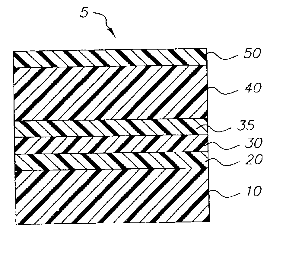
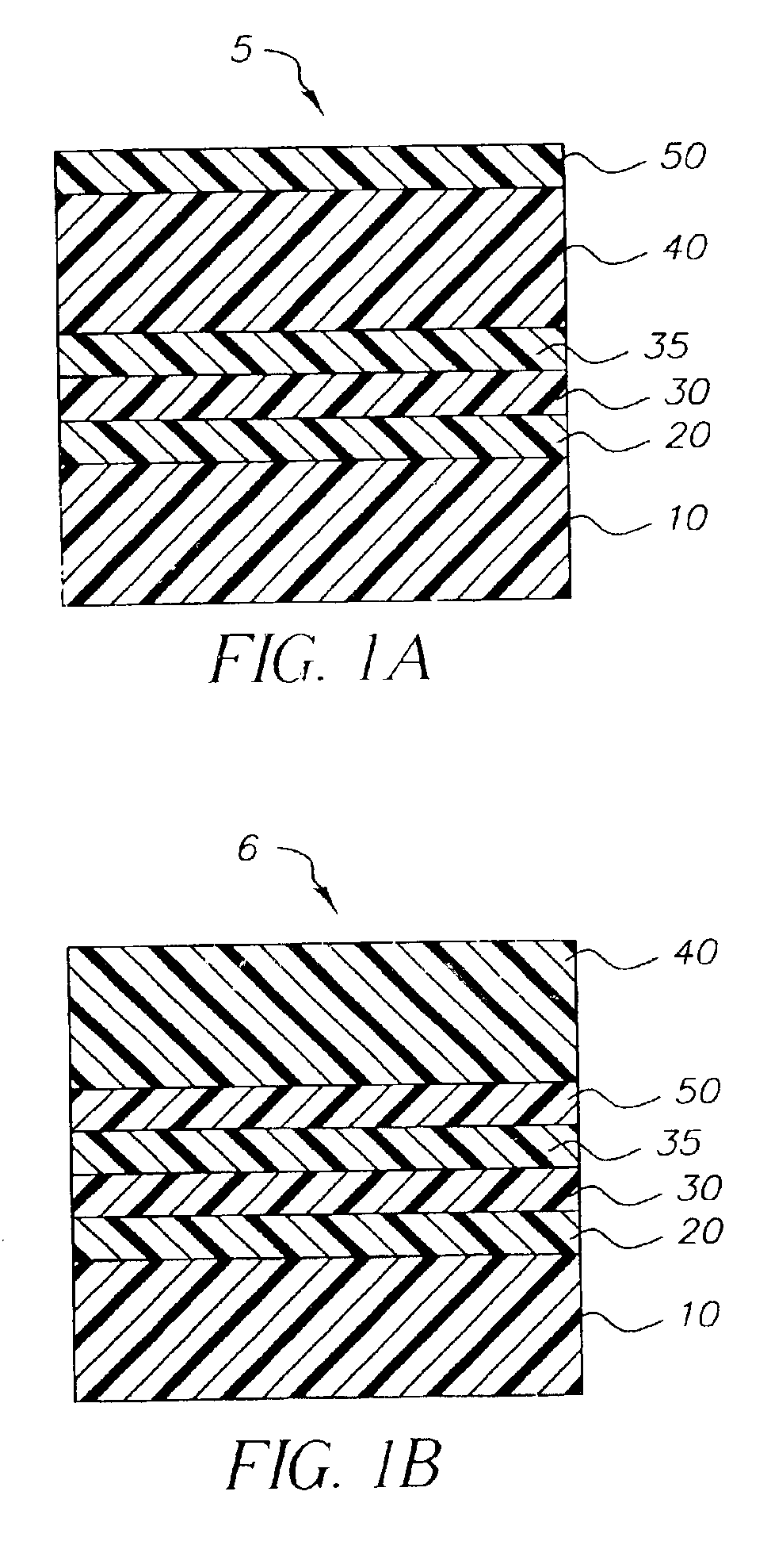
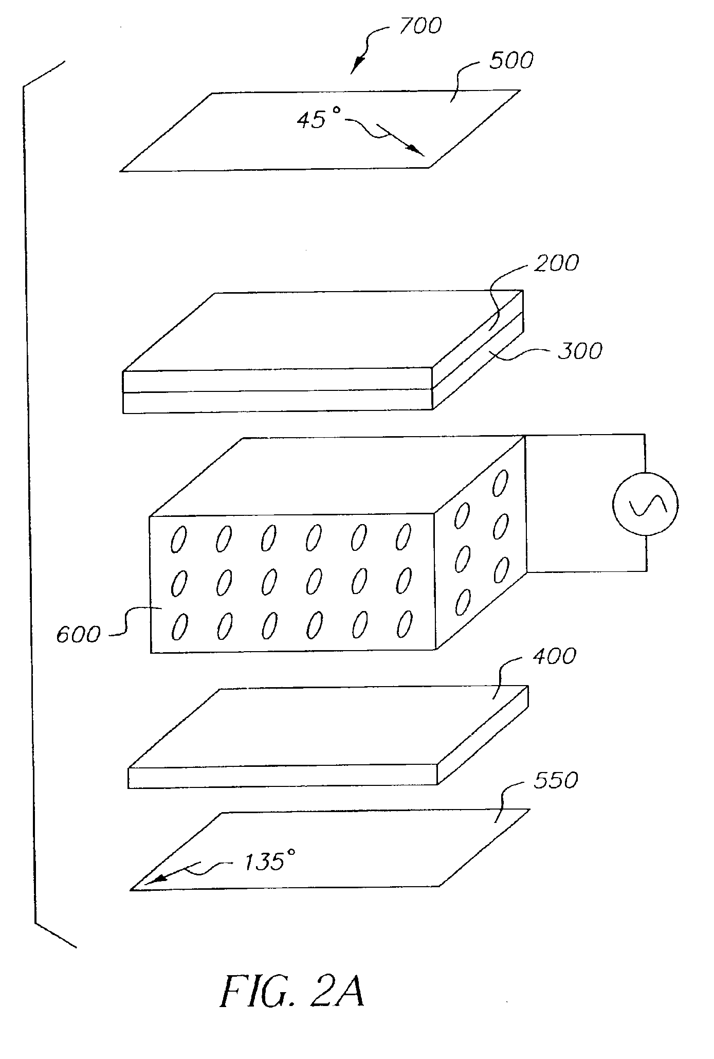
These two orthogonal retardations cannot be independently controlled by this method.
Also, producing uniform optical compensators by this method is described as being difficult.
This limits the potential thickness to be considered for this layer.
This layer must also be pixilated, and this adds additional complications.

Method used


Image

  • Liquid crystal cell with compensator layer and process
  • Liquid crystal cell with compensator layer and process
  • Liquid crystal cell with compensator layer and process

Examples


example 1

Polymer I (Synthesis)

To a stirred mixture of 4,4″-hexafluoroisopropylidenediphenol (33.62 g, 0.1 mole) and triethylamine (22.3 g, 0.22 mole) in methylene chloride (200 mL) at 10° C. was added a solution of terephthaloyl chloride (10.15 g, 0.05 mole) and isophthaloyl chloride (10.15 g, 0.05 mole) in methylene chloride (100 mL). After the addition, the temperature was allowed to rise to room temperature and the solution was stirred under nitrogen for 4 hours, during which time triethylamine hydrochloride precipitated in a gelatinous form and the solution became viscous. The solution was then filtered and washed with dilute hydrochloric acid, (100 mL of 2% acid) followed three times by water (200 mL). The solution was then poured into methanol with vigorous stirring, and a white fibrous polymer precipitated. The glass transition temperature of this polymer was measured by differential scanning calorimetry to be 199° C.

Poly(4,4′-hexafluoroisopropylidene-bisphenol) terephthalate-co-isop...

example 2

Polymer II was similarly prepared using terephthaloyl chloride and 4,4′-(hexahydro-4,7-methanoindan-5-ylidene) bisphenol. The glass transition temperature of this polymer was measured by differential scanning calorimetry to be 289° C.

Poly(4,4′-hexahydro-4,7-methanoindan-5-ylidene bisphenol) terephthalate

Polymer II

When polymer II is spun cast onto a glass substrate (10% solids in dichloroethane), it shows the following optical retardations. Re, Rth and the polymer II layer thickness are measured with an ellipsometer (model M2000V, J.A. Woollam Co.) at 550 nm wavelength.

TABLE IIPolymer II LayerRe, In-PlaneRth, Out-of-Planethickness (μm)Retardation (nm)Retardation (nm)3.40.2−74

example 3

Polymer III was similarly prepared using terephtaloyl chloride, isophthaloyl chloride and 4,4′-isopropylidene-2,2′,6,6′-tetrachlorobisphenol. The glass transition temperature of this polymer was measured by differential scanning calorimetry to be 250° C.

Poly(4,4′-isopropylidene-2,2′6,6′-tetrachlorobisphenol) terephthalate-co-isophthalate

Polymer III

When polymer III is spun cast onto glass (10% solids in dichloroethane), it shows the following optical retardations. Re, Rth and the polymer III layer thickness are measured with an ellipsometer (model M2000V, J.A. Woollam Co.) at 550 nm wavelength.

TABLE IIIPolymer III LayerRe, In PlaneRth, Out of Planethickness (μm)Retardation (nm)Retardation (nm)2.80.8−66


PUM

PropertyMeasurementUnit
thicknessaaaaaaaaaa
thicknessaaaaaaaaaa
thicknessaaaaaaaaaa

Abstract

Disclosed is a liquid crystal cell having contiguous to a surface of a constraint thereof one or more compensator layers, each containing a transparent amorphous polymeric birefringent material having an out-of plane birefringence more negative than −0.005. The invention also provides a liquid crystal display and a process for making such a cell.

Description

FIELD OF THE INVENTIONThe present invention relates to a liquid crystal cell having contiguous to an exterior surface of a constraint thereof a compensator layer containing an amorphous polymeric birefringent material having an out-of plane birefringence more negative than −0.005. The invention also provides an LC display and a process for making such a cell.BACKGROUND OF THE INVENTIONTriacetylcellulose (TAC, also called cellulose triacetate) film has traditionally been used by the photographic industry due to its unique physical properties and flame retardance. TAC film is also the preferred polymer film for use as a cover sheet for the polarizers used in liquid crystal displays. It is the preferred material for this use because of its extremely low in-plane birefringence. Its out of plane birefringence is also small (but not zero), and is useful in providing some optical compensation to the LCD.Intrinsic birefringence describes the fundamental orientation of a material at a molecu...

Claims


Application Information

Patent Timeline
Patent Type & Authority Patents(United States)
IPC IPC(8): C08G63/00C08G63/193C08L67/03C08L67/00G02F1/13G02F1/13363
CPCC08G63/193G02F1/133634C08L67/03
Inventor ELMAN, JAMES F.MASSA, DENNIS J.
Owner NITTO DENKO CORP
Why Eureka
Try Eureka