Comparator circuit for semiconductor test system

a semiconductor test system and comparator circuit technology, applied in the field of comparator circuits, can solve the problems of difficult differential output test, low cost, and easy noise, and achieve the effects of low cost, easy installation, and low cos

Active Publication Date: 2005-02-15
ADVANTEST CORP
View PDF5 Cites 31 Cited by
  • Summary
  • Abstract
  • Description
  • Claims
  • Application Information

AI Technical Summary

Benefits of technology

According to the present invention, the differential comparator circuit can be easily installed in a semiconductor test system existing in the market at low cost. The differential comparator circuit is formed with discrete semiconductor components, rather than an IC chip, thus, can be produced without an expensive semiconductor design and production process. Further, the differential comparator circuit is designed to detect a short term change in the common mode voltage while not being affected by the common mode voltage change.
In the present invention, an activ

Problems solved by technology

A signal level (voltage swing) of these differential devices is small, thereby being susceptible to noise such as common mode voltage fluctuations.
However, under the differential output situation, such a common mode noise is sometimes considered non-defective in a practical use.
However, in the conventional test method, the differential output test is difficult to perform, and DUTs are frequently determined as defective even though the DUTs should be acceptable.
However, it is expensive to produce such custom IC chips through a semiconductor production process and requires a long turn around time before actual IC chips are produced.
Further, there arise a case where a user wants to test a differential device by a test system existing in his laboratory where the test system is not provided with differential comparators.
For replacing the overall pi

Method used


Image

  • Comparator circuit for semiconductor test system
  • Comparator circuit for semiconductor test system
  • Comparator circuit for semiconductor test system

Examples


Embodiment Construction

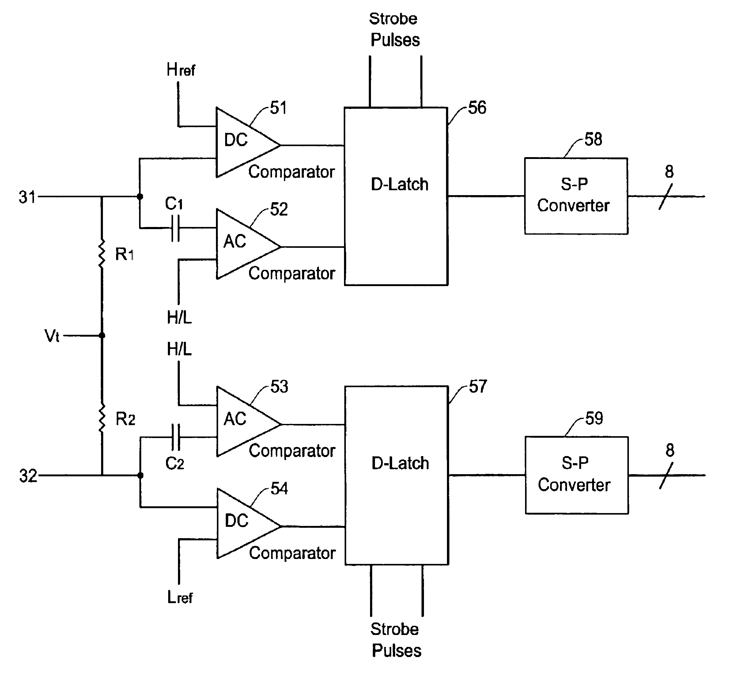
The differential comparator of the present invention will be described here with reference to the accompanying drawings. FIG. 4A shows an example of structure in the differential comparator circuit of the present invention. The differential comparator of the present invention is established with use of discrete component available in the market in, for example, a hybrid IC manner. Thus, it is unnecessary to create a customer IC chip as required in the conventional technology of FIG. 3A.

In the example of FIG. 4A, the differential comparator includes comparators 51-54, strobe D-latches 56 and 57, serial-parallel converters 58 and 59, termination resistors R1 and R2, and capacitors C1 and C2. The capacitor C1 is connected to an input terminal of the comparator 52 and the capacitor C2 is connected to an input terminal of the comparator 53. Thus, the comparators 52 and 53 respectively function as AC comparators while the comparators 51 and 54 respectively function as DC comparators. The ...


PUM


Abstract

A comparator circuit for use in a semiconductor test system for comparing differential output signals of a semiconductor device under test (DUT). The comparator circuit is formed of a first pair of comparators having a DC comparator and an AC comparator which receives a first differential signal, a second pair of comparators having a DC comparator and an AC comparator which receives a second differential signal, a first latch for latching output of the first pair of comparators, a second latch for latching output of the second pair of comparators, and first and second serial-parallel converters for converting output signals of the first and second latches into parallel signals. The comparator circuit is formed of discrete components on a dielectric substrate.

Description

FIELD OF THE INVENTIONThis invention relates to a comparator circuit for use in a semiconductor test system for comparing output signals of a semiconductor device under test (DUT), and more particularly, to a comparator circuit for high speed differential output signals of DUT and having a low cost circuit configuration without requiring an exclusive LSI comparator circuit.BACKGROUND OF THE INVENTIONIn testing semiconductor devices such as ICs and LSIs by a semiconductor test system, a semiconductor device to be tested is placed on a test head and is provided with test signals (test patterns) produced by a pattern generator in the semiconductor test system at its appropriate test pins at predetermined test timings. The semiconductor device under test produces output signals in response to the test signals which are received by the semiconductor test system. The output signals are strobed (sampled) by strobe signals at predetermined timings and are compared with expected output data ...

Claims


Application Information

Patent Timeline
IPC IPC(8): G01R31/28G06F11/00G06F7/02H03K5/22H03M13/00G01R31/3193G06F11/273
CPCG06F11/273G01R31/31932
Inventor FRAME, JAMES W.CHRUSCIEL, RICHARD W.
Owner ADVANTEST CORP
Why Eureka
Try Eureka