Method and apparatus for a power system for phased-array radar

a power system and phased array technology, applied in the field of radio detection and ranging, can solve the problems of ineffective power system, and inability to provide full prime power to all antenna sections

Inactive Publication Date: 2005-02-15
RAYTHEON CO
View PDF13 Cites 57 Cited by
  • Summary
  • Abstract
  • Description
  • Claims
  • Application Information

AI Technical Summary

Benefits of technology

[0018]An input / output common bus fault detector monitors power delivered to and taken from the common bus. The sum of input and output currents to the common DC bus is monitored using Hall effect sensors. Since energy storage capacitors are decoupled from the bus by diodes, at any instant in time, the input and output current should be approximately equal. A ground fault on the common bus manifests itself as a difference between input and output current and the fault can be detected in, for example, a few microseconds.

Problems solved by technology

Conventional phased-array radar technology does not provide power systems capable of providing full power to a single section of the antenna array when needed, nor does it provide power systems having effective current sharing among power supplies.
This arrangement has several disadvantages including that full prime power is not available to all antenna sections.
In the case of the peak power system operating with long, high duty cycle pulses, the conventional arrangement does not enable concentrating full prime power on one specific section of the antenna.
A second disadvantage of the conventional arrangement is that there is inadequate current sharing of parallel redundant power supplies.
Current sharing between three parallel supplies using this approach is not optimum and can be as unbalanced as, for example, 68% load from the first power supply, 31% load from the second power supply, and 1% load from the third power supply.
This approach results in imperfect current sharing, and therefore more power supplies are required.

Method used


Image

  • Method and apparatus for a power system for phased-array radar
  • Method and apparatus for a power system for phased-array radar
  • Method and apparatus for a power system for phased-array radar

Examples


Embodiment Construction

fault in a converter of FIG. 1;

[0028]FIG. 9 is a graph of waveforms under a converter ground fault in a converter of FIG. 1;

[0029]FIG. 10 is a graph of a load fault current and of a fault signal from a first converter and a fault signal from a second converter of the converters of FIG. 1;

[0030]FIG. 11 is a block diagram of a portion of the power system of FIG. 1 including Hall effect sensors to detect a bus fault according to principles of the invention; and,

[0031]FIG. 12 is a block diagram of a generalized system according to principles of the invention having a plurality of power converters and a plurality of loads coupled to a common bus.

DETAILED DESCRIPTION

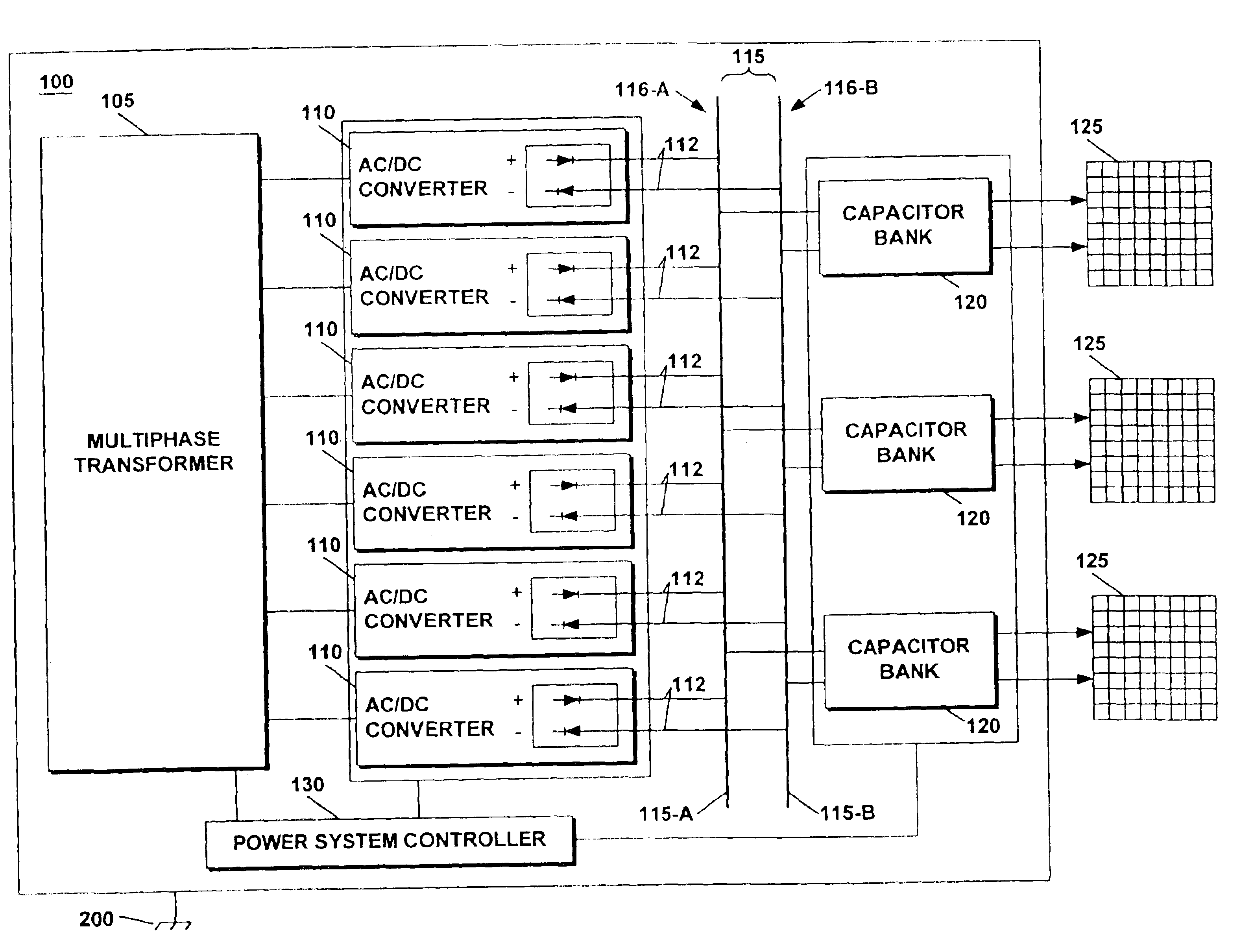
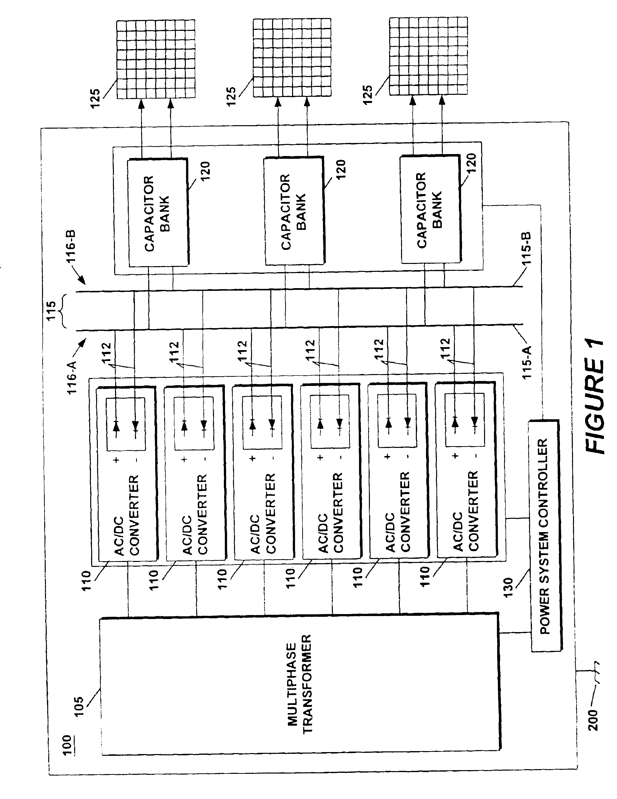
[0032]A power system for a phased-array radar system powers an antenna array with a single multiphase transformer. A plurality of AC / DC converters are connected in parallel between the single multiphase transformer and a common bus. The common bus is balanced with respect to chassis ground reducing noise and improving operatin...


PUM


Abstract

A power system for a phased-array radar system powers an antenna array with a single multiphase transformer. A plurality of AC/DC converters are connected in parallel between the single multiphase transformer and a common bus. The common bus is balanced with respect to chassis ground reducing noise and improving operating safety of the antenna. The AC/DC converters each has a multi-sloped characteristic which enables the converters to share power by modifying output impedance as a function of load without external control signals. The system also has several layers of fault detection.

Description

BACKGROUND OF THE INVENTION[0002]Radar is an acronym for “radio detection and ranging.” A radar system can be used both to detect position and to detect the movement of objects. Radar systems generally operate in the ultra-high-frequency (UHF) or microwave part of the radio-frequency (RF) spectrum. Radar systems are widely used in air-traffic control, aircraft navigation, marine navigation and in detection systems used in military applications. Radar can also track storm systems, because precipitation reflects electromagnetic fields at certain frequencies.[0003]Radar systems use antennas to receive or to send radar signals. In general, an antenna is a device that converts radio-frequency fields into alternating current (AC) or vice-versa.[0004]In electronic signaling, phase is a definition of the position of a point in time (i.e., an instant) on a waveform cycle. A waveform is the representation of how AC varies with time. One example of an AC waveform is the sine wave. The sine wav...

Claims


Application Information

Patent Timeline
Patent Type & Authority Patents(United States)
IPC IPC(8): G01S13/00G01S7/02G01S7/28H01Q3/22H01Q3/26
CPCG01S7/282G01S7/4008G01S2013/0254
Inventor JACOBSON, BORIS SOLOMONMCGINTY, JOHNTHOMAS, PAUL CHRISTIAN
Owner RAYTHEON CO
Why Eureka
Try Eureka