Rotating display system

a display system and rotating technology, applied in the direction of display means, identification means, advertising, etc., can solve the problems of non-uniform display, battery power, and inability to meet the needs of users, and achieve the effect of reducing the number of users

Inactive Publication Date: 2005-02-15
KOWALEWSKI DANIEL L
View PDF15 Cites 65 Cited by
  • Summary
  • Abstract
  • Description
  • Claims
  • Application Information

AI Technical Summary

Benefits of technology

In a further embodiment, various aspects of the display system are microprocessor controlled. This allows flexibility with regards to the operation of the display system, especially considering that the display system includes re-programmable nonvolatile memory. This memory includes program and data space that allow the operation of the display system to be customized and numerous messages and images to be stored and displayed according to the particular program operating the apparatus. The display system may be programmed externally via a computer cable and adapter. This feature all

Problems solved by technology

For example, LED displays placed in motion and modulated in a controlled manner can cause stable characters to appear as the result of a phenomenon known as “persistence of vision.” Practical and inexpensive persistence-of-vision display products, however, are not currently available.
Some device

Method used


Image

  • Rotating display system
  • Rotating display system
  • Rotating display system

Examples


Embodiment Construction

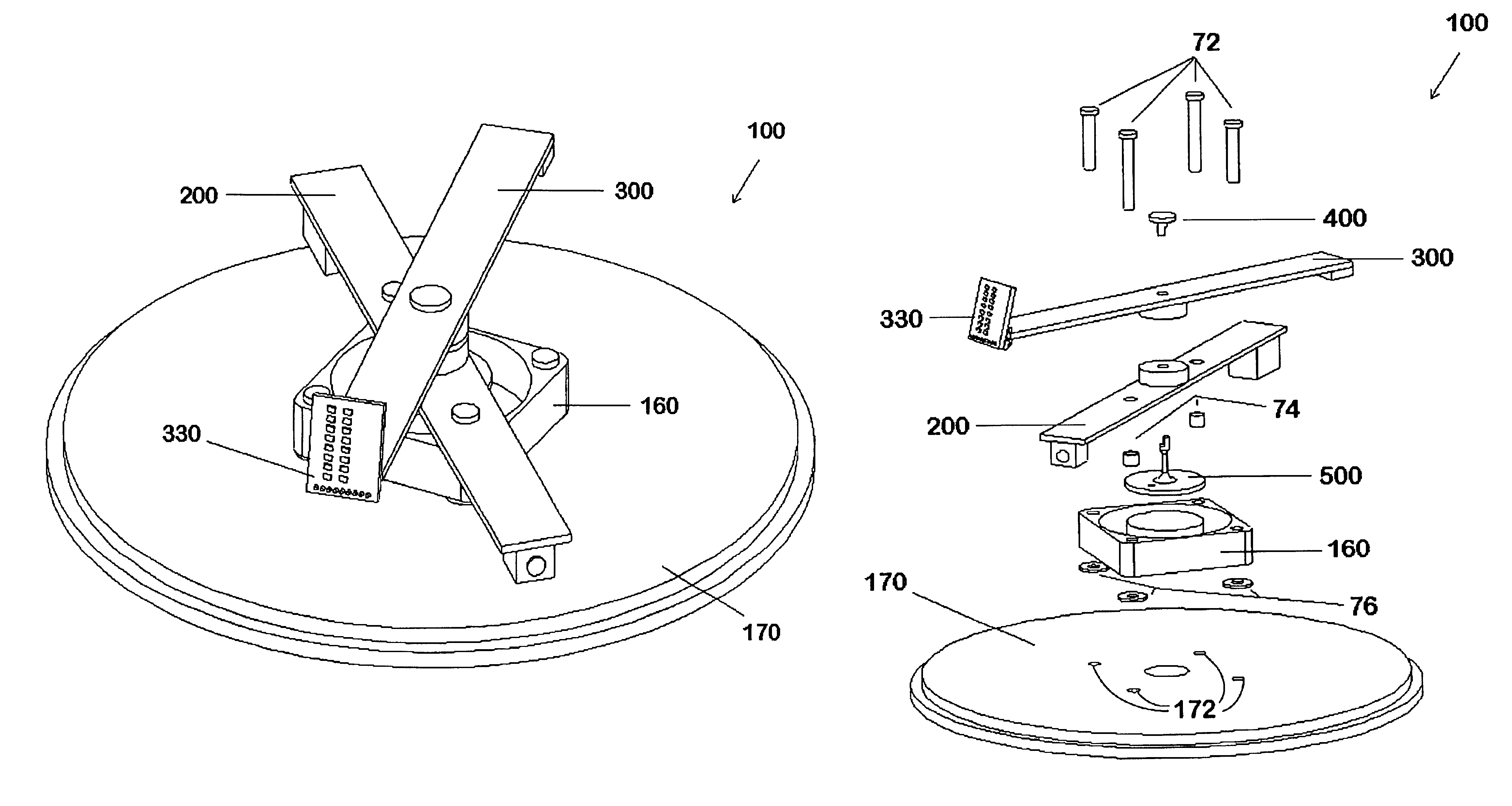
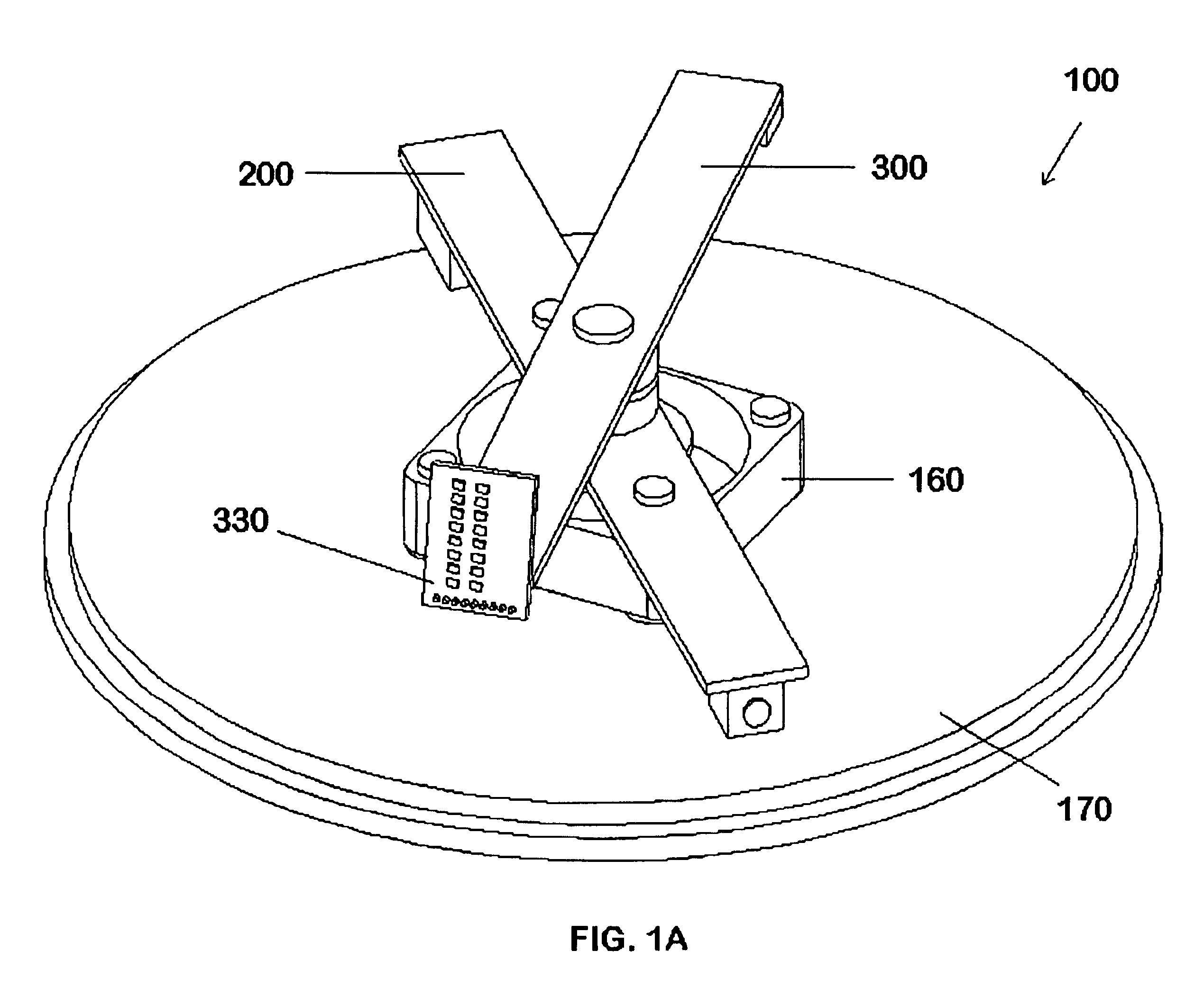
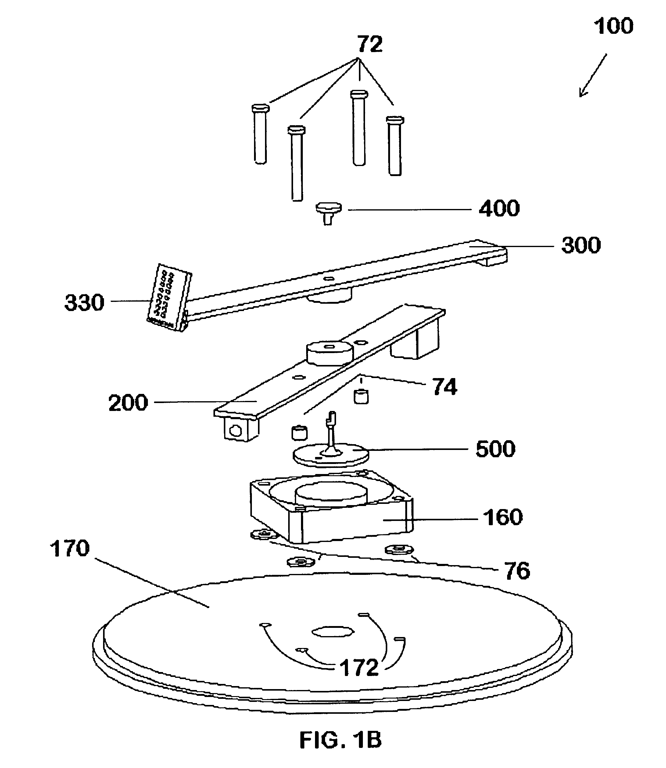
FIGS. 1-12 illustrate a rotating display system 100. In particular, FIGS. 1-5 illustrate mechanical hardware aspects of a rotating display system 100. Also, FIGS. 6-8 illustrate electrical hardware aspects of a rotating display system 100. Further, FIGS. 9-12 illustrate software aspects of a rotating display system 100.

Hardware Configuration

Mechanical

FIGS. 1A-B illustrate a mechanical hardware configuration for a rotating display system 100. As shown in FIG. 1A, the display system 100 has a control assembly 200, a display assembly 300, a light array 330 mounted on the display assembly 300, and a motor 160 mounted on and supported by a base 170. The control assembly 200 has a processor 610 (FIG. 600) that controls display rotation, processes display data and transmits data to the display assembly 300, as described with respect to FIGS. 6, 8 and 11, below. The display assembly 300 has a processor 710 (FIG. 7) that receives display data and formats it for the light array 330, as descri...


PUM


Abstract

A pixel-based display utilizes persistence-of-vision to sweep text and graphics in a cylindrical plane, including time and date, custom messages and animations. The display is generated from a light array with a column of modulated light emitting elements, which is mounted on a rotating display assembly. Power and data are combined on a fixed control assembly and inductively coupled to the display assembly. A control assembly processor interprets a display application language that describes display-specific tasks to generate command, mode, character and graphic data for the display assembly. The control assembly processor also reads a trigger position sensor and adds a trigger delay to generate a virtual trigger command, which provides for flexible display positioning and scrolling display effects.

Description

REFERENCE TO COMPUTER PROGRAM LISTING APPENDIXThis application incorporates by reference a computer program listing appendix, referred to herein as Appendix C and contained on each of two identical CD-R discs submitted herewith as filename: KOWA.001A Appendix.C; size: 24 KB; created: Oct. 22, 2001.BACKGROUND OF THE INVENTIONElectronic displays are pervasive in the modem world. Various incarnations of cathode-ray tube, vacuum florescent, light emitting diode (LED), liquid crystal display (LCD) and more recently laser diode and light valve technologies are applied in electronic devices used to visually transfer information. Common displays typically provide visual information arranged as pixels or vectors in a two-dimensional plane. The information transmitted by the device is usually alphanumeric or graphical in nature. The content of the information is only limited by the imagination of the purveyors.SUMMARY OF THE INVENTIONAdvances in microcontroller technology and electronics in g...

Claims


Application Information

Patent Timeline
IPC IPC(8): G09F9/33G09G3/00
CPCG09G3/005G09F9/33
Inventor KOWALEWSKI, DANIEL L.
Owner KOWALEWSKI DANIEL L
Why Eureka
Try Eureka