It is one object of the invention to provide a polarizer of the type stated in the opening
paragraph hereof characterized by its simple design, low manufacturing costs, and
high transmittance. It is another object to provide a polarizer that is particularly suitable for transforming incident linearly or circularly polarized light into exiting light with an axisymmetric distribution of preferred polarization directions.
If, for example, a small
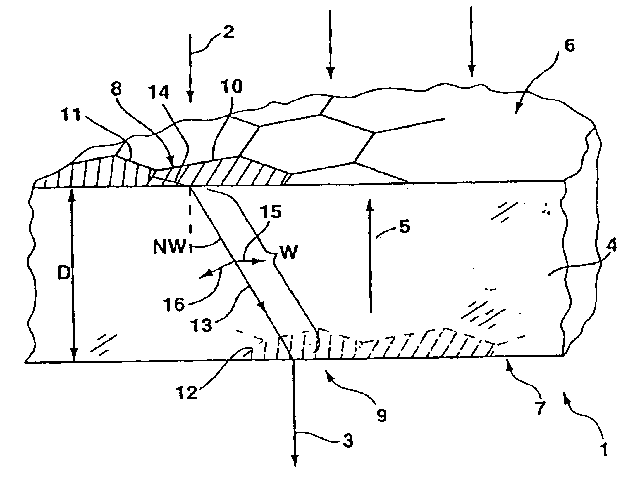
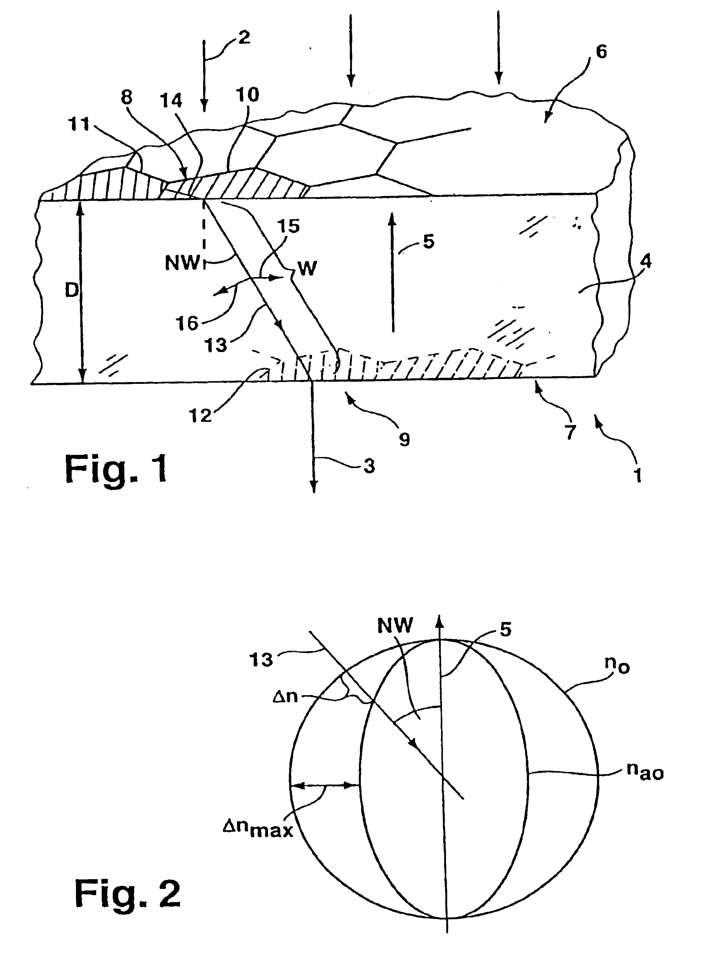
angle of inclination with respect to said crystal axis is set, then the difference in refractive indices, which will be zero along said crystal axis, will be relatively low, which means that the axial thickness will have to be chosen correspondingly large in order to yield a given retardation. Same will simplify the fabrication and handling of polarizers according to the invention, which may be fabricated in the form of loose components, if desired. The choice of axial thickness may be utilized to adapt the operation of the polarizer to the polarization state of light incident on same and the desired polarization distribution for light exiting same. If, for example, a retardation of one-quarter of the
wavelength of said light has been set, then circularly polarized light incident on said polarizer may be transformed into
linearly polarized light exiting its exit face by each of said zones. Altering the direction of said inclination will allow orienting the preferred polarization direction over the
exit plane for each such zone, for example orienting same either tangentially or radially with respect to the polarizer's
optical axis. Setting a half-wave retardation will allow locally rotating the plane of polarization of transmitted
linearly polarized light relative to that of incident
linearly polarized light, where the plane of polarization of said transmitted linearly polarized light may, in turn, be oriented with respect to the
optical axis, preferably either tangentially or radially oriented with respect to same, through suitable choices of the local directions of inclination within said zones.
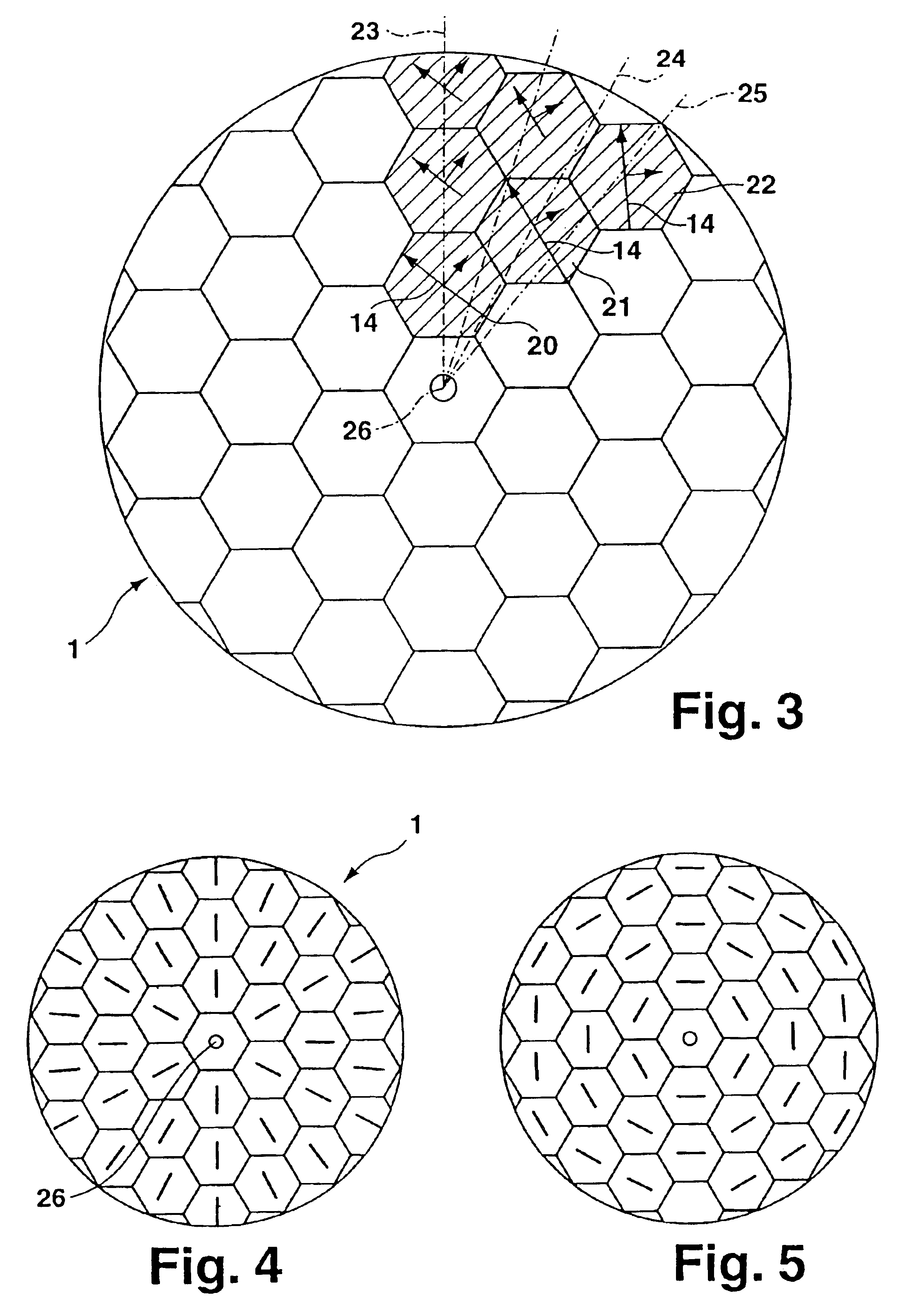
A beneficial advance thereon is distinguished by the fact that it has a birefringent element with its crystal axis oriented roughly parallel to the polarizer's optical axis and that a deflecting structure that deflects incident light such that it transits each of said zones at the inclination angle and direction chosen for that zone is assigned to each of said zones of said birefringent element, which will allow configuring a simply designed, particularly readily fabricated, unsegmented polarizer using a single birefringent element covering the entire cross-section of said polarizer.
It will be useful if the illuminated cross-section of said polarizer is subdivided into small fields or zones, e.g., small hexagonal zones, of constant deflection that more or less cover the entire illuminated cross-section of said polarizer. Other, preferably polygonal-shaped, zones, e.g., square or triangular zones, are possible. The total number of said fields or zones should preferably range from 10 to 100 or more in order that said zones will typically have cross-sectional areas occupying an average of less than 10%, preferably 1% to 10%, of the total cross-sectional area of said polarizer, where the dimensions of said zones may be adjusted to suit the directional tolerances on the desired, local, preferred, polarization direction, which, in the case of the preferred embodiment of said polarizer, will be roughly ±2% or less. Employing smaller-sized zones will allow attaining a nearly continuous distribution of the desired, local, tangential or radial polarizations. Structures having continuous transitions from zone to zone and no well-defined zonal boundaries represent another possibility. It will also be possible to leave narrow vacant spaces between said active zones, which will be tolerable, particularly when said polarizer is employed on illumination systems.
The invention also relates to a microlithographic
projection system incorporating at least one polarizer according to same. Said
projection system has an illumination device equipped with a
light source, for example, a
laser, for illuminating a
mask, where said illumination device is followed by a
projection lens for imaging a pattern borne on said
mask onto the
image plane of said
projection lens, where the item to be structured, for example, a
wafer coated with a layer of
photoresist, is situated. Incorporating one or more polarizers according to the invention will allow fully utilizing the capabilities of the
optics involved. For example, using a polarizer to radially polarize the transmitted beam will improve the efficiency and homogeneity with which light is coupled into said layer of
photoresist, since reflections by said
photoresist and all those lenses that follow said polarizer in the optical
train will be uniformly reduced. For light incident at large angles less than the Brewster angle, said effect will be most pronounced wherever the
light intensity is lowest due to the decline in
light intensity that occurs near the edges of the illuminated area. Any adverse effects on spatial resolution due to
scattered light, included light scattered at the interface between said photoresist and said
wafer, will be homogenized and reduced.
On the other hand, tangential polarization may be beneficial in cases where anti-reflection-coated photoresists and very high image-side numerical apertures are employed, in which case, interference-fringe contrast will be the determining factor. Interference-fringe contrast will be maximized when dual-beam interference of a pair of beams whose polarizations are oriented orthogonal with respect to the
plane of incidence occurs. It has been found that tangential polarization allows markedly increasing interference-fringe contrast.
