Method of manufacturing an electrolytic cell

a manufacturing method and electrolytic cell technology, applied in the field of manufacturing electrolytic cells, can solve the problems of low production yield, less than 40%, and prone to shorting of electrolytic cells after sintering, and achieve the effect of preventing shorting between the anode and the cathode layer

Inactive Publication Date: 2005-02-22
PRAXAIR TECH INC
View PDF11 Cites 15 Cited by
  • Summary
  • Abstract
  • Description
  • Claims
  • Application Information

AI Technical Summary

Benefits of technology

Unlike the prior art, the electrolyte layer is fully sintered and a substance is introduced to plug the defects. In such a simple manner, electrical shorting between the anode and cathode layers is prevented.

Problems solved by technology

In current manufacturing technologies, electrolytic cells are prone to shorting after sintering.
In fact, manufacturing yields can be quite low, less than 40%.
The reason for the low productivity is believed to be related to the fact that the dense electrolyte film is typically very thin, about 25 microns, and cannot sinter to 100% of its theoretical density using current available technology.
Plugs formed by impregnation of a metal solution or special precursor into pores of the electrolyte can leave gaps within the electrolyte due to shrinkage during firing.
As a result, defects will be produced by the resultant gaps.
EVD processing has the disadvantage of taking time and thereby decreasing production rate.
Additionally, EVD adds expense to the production by increasing the initial capital investment involved in obtaining the necessary equipment.

Method used


Image

  • Method of manufacturing an electrolytic cell
  • Method of manufacturing an electrolytic cell
  • Method of manufacturing an electrolytic cell

Examples


example 1

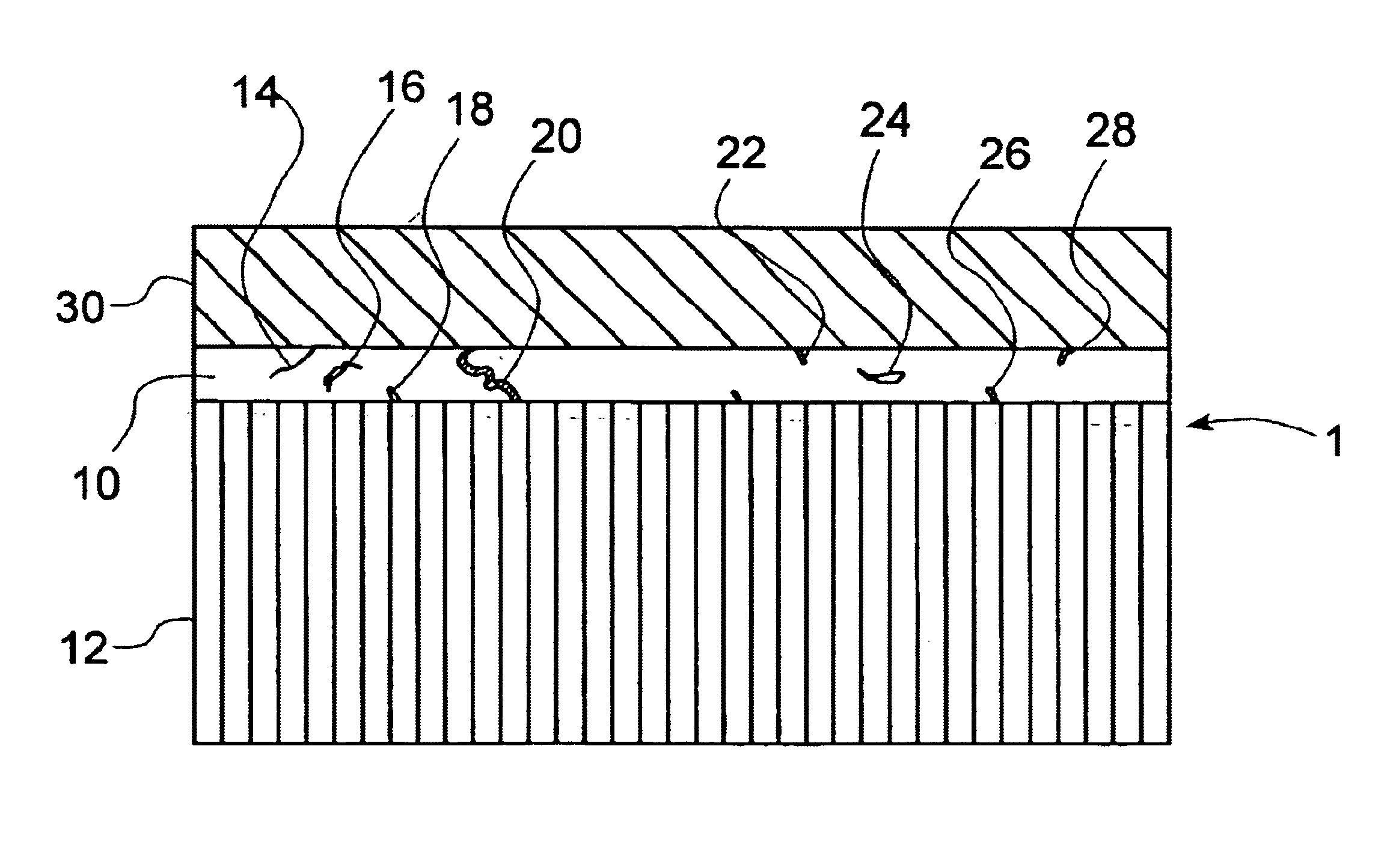
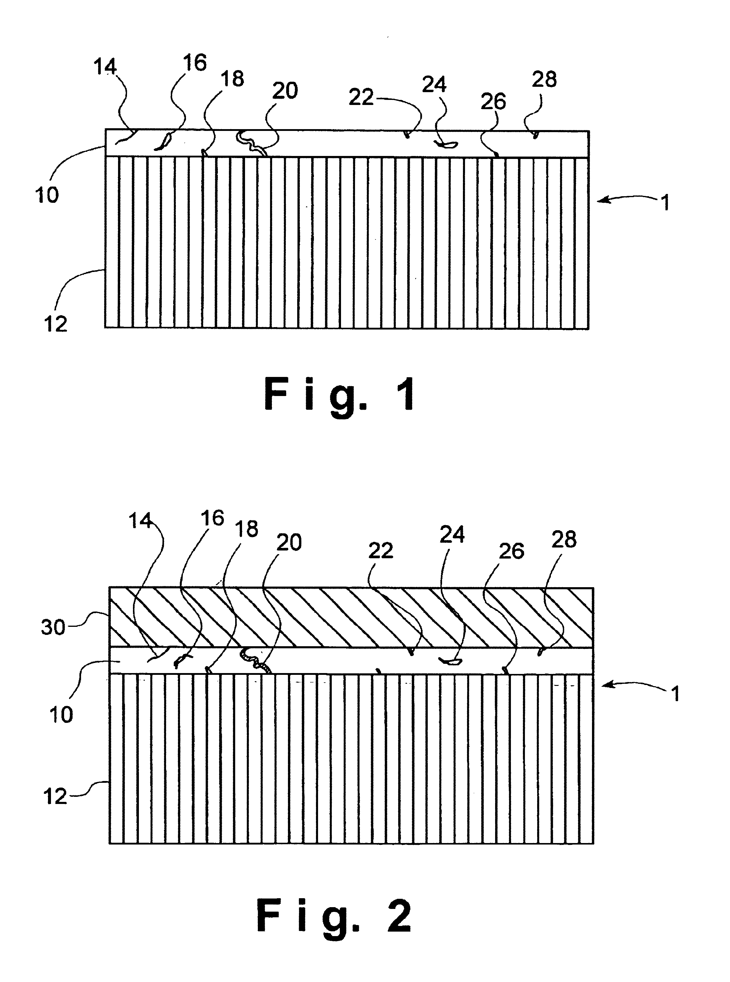
An electrolytic cell was fabricated in accordance with prior art techniques and without utilization of the present invention. The intermediate sintered form produced in the manner outlined above, was dipped into a slurry solution containing LSCF and allowed to soak for a few seconds. The coated tube was then carefully drawn out of the slurry and allowed to partially dry in a fume hood for about 5 minutes. Thereafter, the tube was completely dried in an oven at a temperature of about 200° C. for abut 30 minutes. The dried tube was finally loaded into a furnace and heated at about 1° C. per minute under ambient air to about 450° C. and held at such temperature for about 1 hour to remove the organic binder in the coating. The heating ramp was increased to 2° C. per minute to about 900° C. for 4 hours to sinter the coating. The furnace was cooled to room temperature at the rate of 2° C. per minute. The cathode layer 30 prepared in this manner was found to be porous with a porosity of fr...

example 2

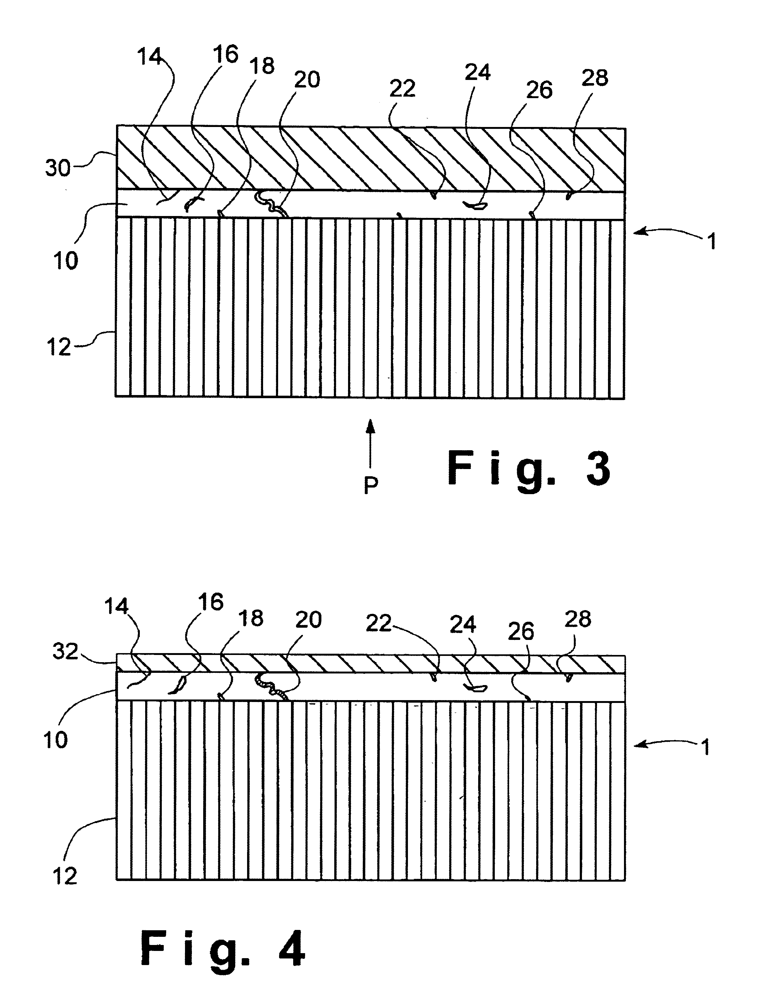
An electrolytic cell was fabricated in accordance with the current invention. The sintered intermediate tube was formed in the manner outlined above and a cathode layer 30 was applied in the manner outlined in Example 1. The tube was attached to an air source and 4 psi pressure was applied to the inside of the tube which was maintained during the entire processing steps of Example 1. The cathode coating prepared this way was found to be porous with a porosity of between about 30% and about 40% and a thickness of about 50 microns.

The resultant electrolytic cell was then evaluated for shorting by performing a RT resistance test. The resistance was found to be 3.7 MΩ. The electrolytic cell was considered to be non-electrically shorted and therefore passed inspection.

example 3

A sintered intermediate form was prepared in the manner described above and was attached to an air source. A 4-psi pressure was applied to the inside of the tube. The tube was then dipped into a slurry solution containing about 50% by weight of LSCF and about 50% by weight of Ag. After a few seconds had elapsed, the coated tube was carefully drawn out of the slurry and allowed to partially dry in a fume hood for about 5 minutes. The tube was completely dried in an oven of about 200° C. for about 30 minutes. During the entire drying process, the air pressure inside the tube was maintained at about 4 psi. The dried tube was disconnected with the air source and loaded into a furnace. It was heated at about 1° C. per minute in ambient air to about 450° C. and held at such a temperature for about 1 hour to remove the organic binder in the coating. The heating ramp was increased to about 2° C. per minute to about 900° C. and held for 4 hours to sinter the coating. The furnace was cooled t...


PUM

PropertyMeasurementUnit
thicknessaaaaaaaaaa
thicknessaaaaaaaaaa
sizeaaaaaaaaaa

Abstract

A method of manufacturing an electrolytic cell in which an intermediate sintered form is produced that comprises a porous anode layer and an electrolyte layer having a prespecified shape of the electrolytic cell. The electrolyte layer has defects extending through the electrolyte layer. A substance by way of a pressure, a solvent, particle suspended in a solvent or particles introduced by way of thermal spray are introduced into defects within the electrolyte layer. Thereafter, a green cathode layer is applied to the electrolyte layer while the substance is in place, within the defects. The intermediate sintered form with the applied green cathode layer is then fired to produce the electrolytic cell.

Description

FIELD OF THE INVENTIONThe present invention relates to a method of manufacturing an electrolytic cell of the type that employs an electrolyte that conducts oxygen ions to separate oxygen when an electrical potential is applied across the electrolyte. More particularly, the present invention relates to such a method in which a substance is introduced into defects within the electrolyte during formation of the electrolytic cell to prevent such defects from becoming pathways for electrical shorting of the electrolytic cell.BACKGROUND OF THE INVENTIONAn electrolytic cell is a layered structure that has anode and cathode electrode layers sandwiching an electrolyte layer that is formed of a solid oxide such as yttria stabilized zirconia or gadolinium doped ceria. When an electrical potential is applied across to the electrodes, oxygen, in an oxygen containing feed, ionizes to produce oxygen ions which are transported through the electrolyte. The oxygen ions emerge from the electrolyte and...

Claims


Application Information

Patent Timeline
Patent Type & Authority Patents(United States)
IPC IPC(8): C04B33/32H01M2/14C04B35/26C25B9/00H01M4/88H01M8/12
CPCC04B35/2608C25B9/00H01M4/8885H01M8/1213C04B35/6264Y10T29/49108C04B2235/3213C04B2235/3224C04B2235/3227C04B2235/3229C04B2235/3275C04B2235/5436C04B2235/604C04B2235/94C04B2235/96H01M2008/1293Y02E60/521Y02E60/525Y10T29/49115Y02E60/50Y02P70/50
Inventor CHEN, HANCUNWANG, WEITUNG
Owner PRAXAIR TECH INC
Why Eureka
Try Eureka