
Plasma enhanced chemical deposition for high and/or low index of refraction polymers

a technology of refraction polymer and enhanced chemical deposition, which is applied in the direction of coating, chemical vapor deposition coating, and plasma technique, etc., can solve the problems of difficult control of metering of gas, low deposition rate, and two sequential steps, and achieve enhanced chemical vapor deposition

Inactive Publication Date: 2005-02-22
SAMSUNG DISPLAY CO LTD
View PDF110 Cites 37 Cited by
  • Summary
  • Abstract
  • Description
  • Claims
  • Application Information

AI Technical Summary

Benefits of technology

The present invention may be viewed as a method for plasma enhanced chemical vapor deposition of low vapor pressure polymer precursor or a mixture of polymer precursor with particle materials onto a substrate, or as a method for making self-curing polymer layers, especially self-curing PML polymer layers. From both points of view, the invention is a combination of flash evaporation with plasma enhanced chemical vapor deposition (PECVD) that provides the unexpected improvements of permitting use of low vapor pressure polymer precursor materials in a PECVD process and provides a self-curing polymer from a flash evaporation process, at a rate surprisingly faster than standard PECVD deposition rates.

Problems solved by technology

Because these high vapor pressure monomeric gases do not readily cryocondense at ambient or elevated temperatures, deposition rates are low (a few tenths of micrometer / min maximum) relying on radicals chemically bonding to the surface of interest instead of cryocondensation.
Lower vapor pressure species have not been used in PECVD because heating the higher molecular weight monomers to a temperature sufficient to vaporize them generally causes a reaction prior to vaporization, or metering of the gas becomes difficult to control, either of which is inoperative.
A disadvantage of the flash evaporation is that it requires two sequential steps, cryocondensation followed by curing or cross linking, that are both spatially and temporally separate.
However, multi-ring system compounds that are solids are not useful as a monomer in these systems.
However, bromine adds a brown color and tends to oxidize over time, and fluorinated monomers have high vapor pressures, poor adhesion and high cost.

Method used


Image

  • Plasma enhanced chemical deposition for high and/or low index of refraction polymers
  • Plasma enhanced chemical deposition for high and/or low index of refraction polymers
  • Plasma enhanced chemical deposition for high and/or low index of refraction polymers

Examples


Embodiment Construction

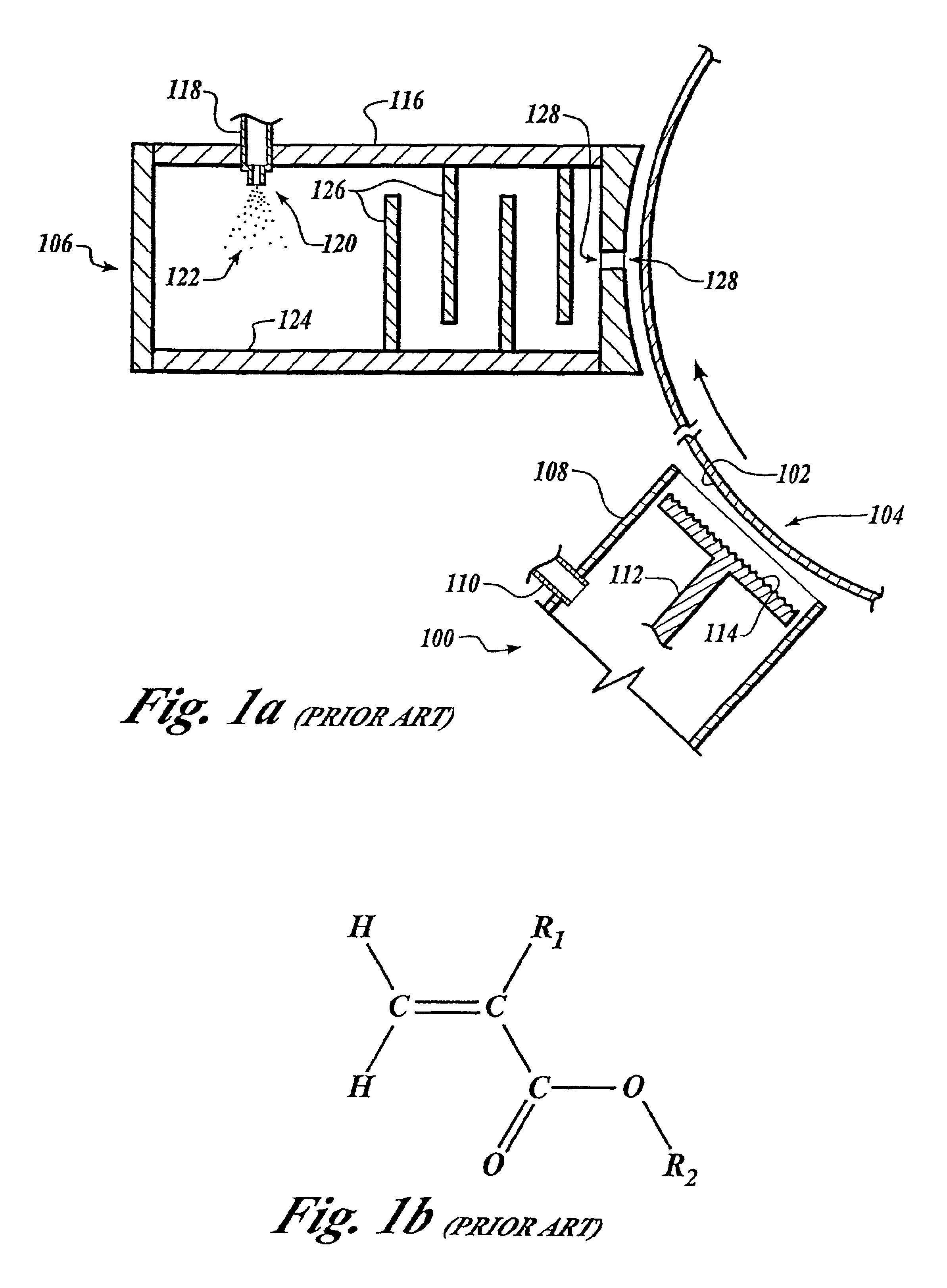
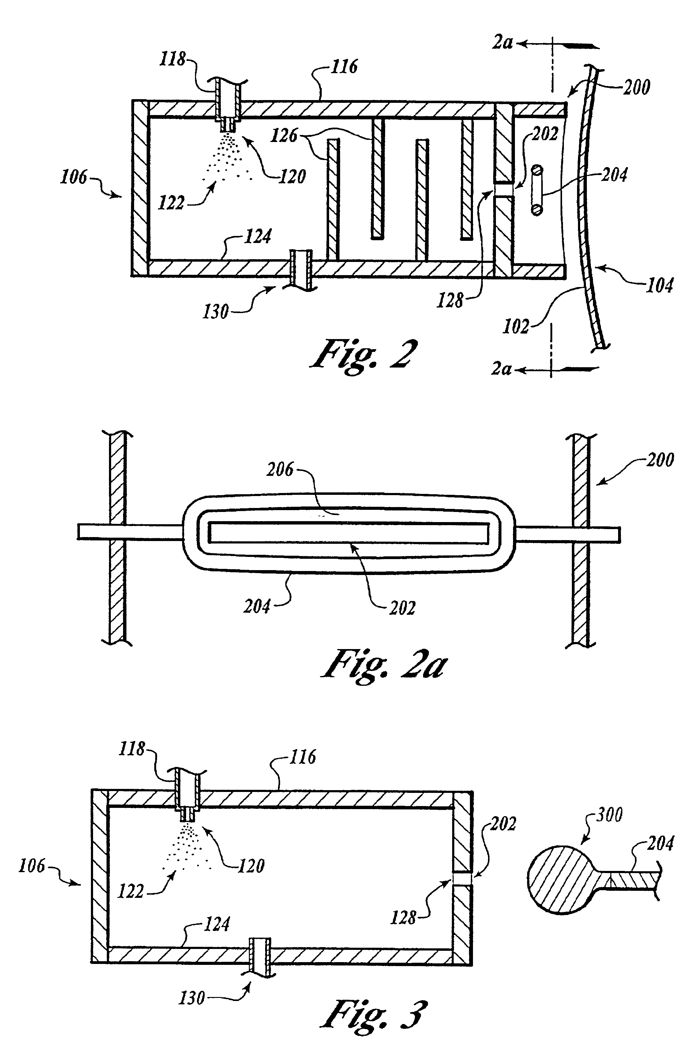
An apparatus which can be used in the method of the present invention is shown in FIG. 2. The method of the present invention may be performed within a low pressure (vacuum) environment or chamber. Pressures typically range from about 10−1 torr to 10−6 torr, although higher or lower pressures can be used. The flash evaporator 106 has a housing 116, with a polymer precursor inlet 118 and an atomizing nozzle 120. Flow through the nozzle 120 is atomized into particles or droplets 122 which strike the heated surface 124 whereupon the particles or droplets 122 are flash evaporated into a gas or evaporate that flows past a series of baffles 126 to an evaporate outlet 128 and cryocondenses on the surface 102. Cryocondensation on the baffles 126 and other internal surfaces is prevented by heating the baffles 126 and other surfaces to a temperature in excess of a cryocondensation temperature or dew point of the evaporate. Although other gas flow distribution arrangements have been used, it h...


PUM

PropertyMeasurementUnit
Sizeaaaaaaaaaa
Sizeaaaaaaaaaa
Temperatureaaaaaaaaaa

Abstract

A method for making a polymer layer with a selected index of refraction. The method includes flash evaporating a polymer precursor material capable of cross linking into a polymer with the selected index of refraction, forming an evaporate, passing the evaporate to a glow discharge electrode creating a glow discharge polymer precursor plasma from the evaporate, and cryocondensing the glow discharge polymer precursor plasma on a substrate as a condensate and crosslinking the condensate thereon, the crosslinking resulting from radicals created in the glow discharge polymer precursor plasma, forming a polymer having the selected index of refraction.

Description

FIELD OF THE INVENTIONThis application is a continuation in part of application Ser. No. 09 / 212,776 now U.S. Pat. No. 6,207,238, filed Dec. 16, 1998, entitled “Plasma Enhanced Chemical Deposition for High and / or Low Index of Refraction Polymers.”The present invention relates generally to a method of making plasma polymerized films having a specified index of refraction. More specifically, the present invention relates to selecting certain polymer precursors to obtain a desired index of refraction of a plasma polymerized polymer film via plasma enhanced chemical deposition with a flash evaporated feed source of a low vapor pressure compound.As used herein, the term “(meth)acrylic” is defined as “acrylic or methacrylic.” Also, “(meth)acrylate” is defined as “acrylate or methacrylate.”As used herein, the term “cryocondense” and forms thereof refers to the physical phenomenon of a phase change from a gas phase to a liquid phase upon the gas contacting a surface having a temperature lowe...

Claims


Application Information

Patent Timeline
IPC IPC(8): B05D7/24C08G83/00C23C16/50
CPCB05D1/62
Inventor AFFINITO, JOHN D.GRAFF, GORDON L.MARTIN, PETER M.GROSS, MARK E.BURROWS, PAUL E.SAPOCHAK, LINDA S.
Owner SAMSUNG DISPLAY CO LTD
Learn More