
Super resolution microscope

a microscope and super resolution technology, applied in the field of microscopes, can solve the problems of deteriorating image quality, super resolution, and difficulty in distinguishing from them with optical filters and electrical gate control as desired, and achieve the effect of high resolution

Inactive Publication Date: 2005-02-22
JAPAN SCI & TECH CORP +1
View PDF6 Cites 34 Cited by
  • Summary
  • Abstract
  • Description
  • Claims
  • Application Information

AI Technical Summary

Benefits of technology

[0034]It is an object of the present invention to provide a sophisticated microscope using lights of two wavelengths including at least infrared ray or near infrared ray where one light corresponds to the resonance wavelength between the ground state and a given vibration state of a molecule or a given crystalline structure in a sample, and the other light corresponds to an exciting wavelength between the given excited state and a higher electron excited state, and then, by observing the optical response from a narrower region than the diffraction limit, a given chemical group of the sample, which is characterized by a given vibration state, is detected in high resolution.
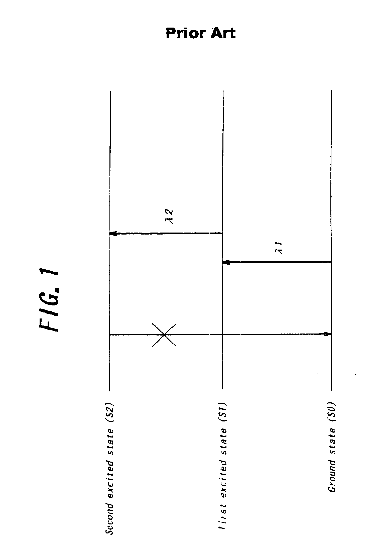
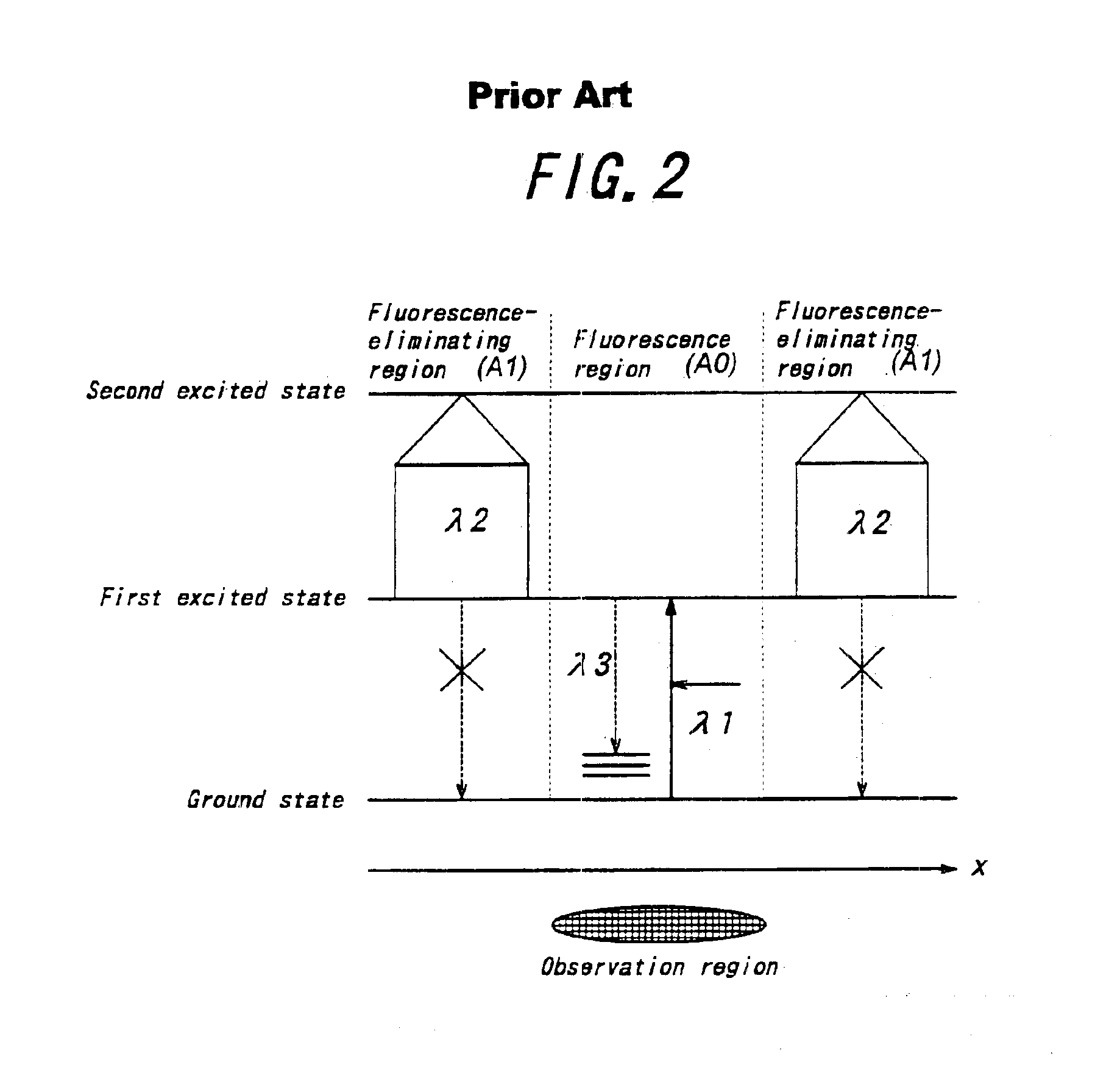
[0042]In the preferred embodiment of the present invention, a first light and a second light which have their respective different wavelengths are employed, and at least one of the lights is composed of a infrared light or near infrared light. Then, the lights are overlapped partially and spatially and then, irradiated onto the sample. In this case, the wavelength of the infrared light or the near infrared light is set to a resonance wavelength to excite the molecule or the crystalline structure of the sample to the given vibration state, and the wavelength of the other light is set to a wavelength to excite to a higher energy level electron excited state from the vibration state, and by observing an optical response (fluorescence) from the sample at the time when the lights are irradiated, a given chemical group which is characterized by the vibration state is detected in high resolution.
[0051]The use of the infrared light or the near infrared light enables almost the same information as that of a conventional fluorescent microscope to be obtained without the dye of a sample such as the biogenic organism with the fluorescent dye molecules. As mentioned above, the vibration absorption spectrum of a given chemical group is sensitive to the surrounding environment, and thus, is changed in structure. In view of the above-mentioned property of the vibration absorption spectrum, the use of the infrared light or the near infrared light enables the existence condition of the substance as well as the material structure of the substance to be clarified. Therefore, the combination of the excellent analysis performance due to the use of the infrared light or the near infrared light and the (infrared) double-resonance absorption process enables the spatial resolution of the microscope to be developed.
[0055]Therefore, the infrared double resonance absorption process is characterized by the high detection sensitivity. For example, in an infrared or a near infrared spectroscopy, an absorption spectrum within an infrared or a near infrared wavelength region is measured, but the change in intensity of the absorption spectrum can not be detected precisely if the absorption degree is small due to the intensity fluctuation of a light source. On the contrary, in the infrared double resonance absorption process, since the side-products are created only by irradiating the pumping light and the probe light into a sample, various phenomena can be easily detected. This process is called as a “zero-level detection”, which is employed in a field of fluorescent microscope, photoelectron microscope or fluorescent X-ray analysis. Moreover, the sensitivity of the detection process using the infrared double resonance absorption is very high.
[0062]In this case, since the wavelength of the probe light is longer, the damage in the sample to be observed can be alleviated, and various laser source commercially available may be employed. For example, an Ar laser (476.5 nm) may be employed as the prove light having the wavelength of 475 nm, and an AlGaAs-based semiconductor laser commercially available, which is not expensive and high reliable, may be employed as the pumping light having the wavelength of 900 nm.
[0065]Various overlapping method for the beam region patterns of the pumping light and the probe light can be considered. As shown in FIGS. 13(a)-(c), for example, the pumping light and the probe light are divided into two regions relating their respective phase modes on the sample, and then, partially overlapped on the sample. In this case, the spatial resolution can be enhanced two times laterally on the sample. Moreover, as shown in FIGS. 14(a)-(c), the two divided beam regions of the pumping light and the probe light are spatially overlapped on the sample longitudinally and laterally, and thus, the spatial resolution can be enhanced longitudinally and laterally. In this case, the two divided beam regions are partially and laterally overlapped in the same manner as shown in FIG. 13, and also, partially and longitudinally shifted each other, to restrict the overlapping region. For example, longitudinal half pitch shift enables the spatial resolution to be enhanced two times.

Problems solved by technology

Since such a side-fluorescence signal is superimposed and mixed with the inherent florescence signal to be observed, it is difficult to distinguish from them with an optical filter and electrical gate control as desired.
As a result, the intensity of back ground signal is increased and thus, the super resolution and the image quality may be deteriorated.

Method used


Image

  • Super resolution microscope
  • Super resolution microscope
  • Super resolution microscope

Examples


Embodiment Construction

4c are views showing a further state where a pumping light and an erasing light are irradiated simultaneously,

[0090]FIG. 15 is a view showing an emission timing between a pumping light and an erasing light in a conventional super resolution microscope,

[0091]FIG. 16 is a view showing another emission timing between a pumping light and an erasing light in a conventional super resolution microscope,

[0092]FIG. 17 is an explanatory view of the principle in a preferred embodiment of a microscope according to the present invention,

[0093]FIG. 18 is another explanatory view of the principle in a preferred embodiment of a microscope according to the present invention,

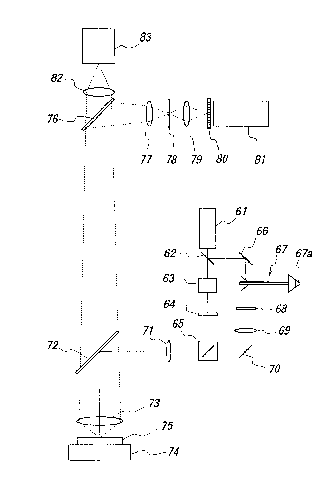
[0094]FIG. 19 is a structural view schematically showing a super resolution microscope using infrared double resonance absorption process in an embodiment of a microscope according to the present invention,

[0095]FIG. 20a, FIG. 20b and FIG. 20c are views showing a structure of the phase plate for the pumping light shown in FIG. 19...


PUM


Abstract

A microscope includes a first light source to emit a first light to excite a molecule of a sample to a higher energy level vibration state which belongs to a lowest energy level electron state from the ground state, a second light source to emit a second light source to excite the molecule to a higher energy level quantum state from the higher energy vibration state, an optical system to overlap the first light and the second light partially on the sample, and an optical detector to detect a given fluorescence from the irradiated region of the first light and the second light on the sample.

Description

BACKGROUND OF THE INVENTION[0002]1. Field of the Invention[0003]The present invention relates to a microscope, particularly a sophisticated microscope using lights of two wavelengths including at least infrared ray or near infrared ray where one light corresponds to the resonance wavelength between the ground state and a given vibration state of a molecule or a given crystalline structure in a sample, and the other light corresponds to an exciting wavelength between the given excited state and a higher electron excited state, and then, by overlapping the lights partially in space and irradiating on the sample, an optical response (e.g., fluorescence) from the sample is observed in a minute region smaller than the diffraction limit of the resulting overlapped light, to detect a chemical group of the sample supersensitively which is characterized by a given vibration.[0004]This invention also relates to a microscope using two kinds of light such as a pumping light and an erasing light...

Claims


Application Information

Patent Timeline
Patent Type & Authority Patents(United States)
IPC IPC(8): G02B21/00G02B21/06
CPCG02B21/06
Inventor IKETAKI, YOSHINORIFUJII, MASAAKIOMATSU, TAKASHIGEYAMAMOTO, KIMIHISASUZUKI, TOSHIO
Owner JAPAN SCI & TECH CORP
Learn More