
Hybrid optical transmitter with electroabsorption modulator and semiconductor optical amplifier

a technology of optical transmitter and modulator, applied in the direction of electromagnetic transmission, semiconductor amplifier structure, semiconductor laser, etc., can solve the problems of limited output power, adversely affecting the output power and signal quality of the ld-eam combination, etc., to achieve better signal quality, increase the launch power of the module, and improve the effect of signal quality

Inactive Publication Date: 2005-03-01
BROADCOM INT PTE LTD
View PDF32 Cites 25 Cited by
  • Summary
  • Abstract
  • Description
  • Claims
  • Application Information

AI Technical Summary

Benefits of technology

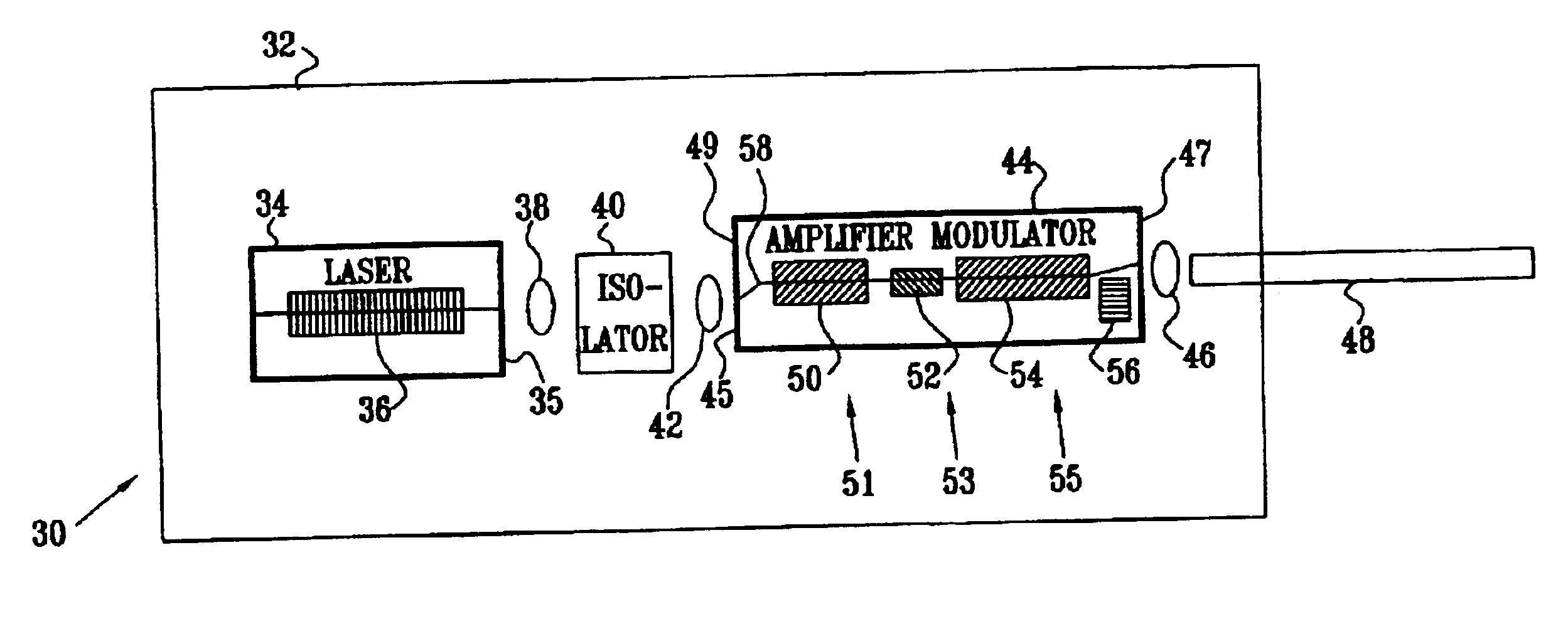
In preferred embodiments of the present invention, a semiconductor laser transmits coherent radiation via an isolator to a combined semiconductor optical amplifier (SOA) and electro-absorption modulator (EAM) device. The semiconductor laser, the isolator, and the combined SOA-EAM device are implemented as one hybrid integrated module. The combined SOA-EAM device in the module amplifies and modulates the radiation from the semiconductor laser. The output from the hybrid module is coupled to an output fiber optic, with higher launch power and better signal quality, as measured by the frequency response, extinction ratio, and chirp, compared to systems known in the art.
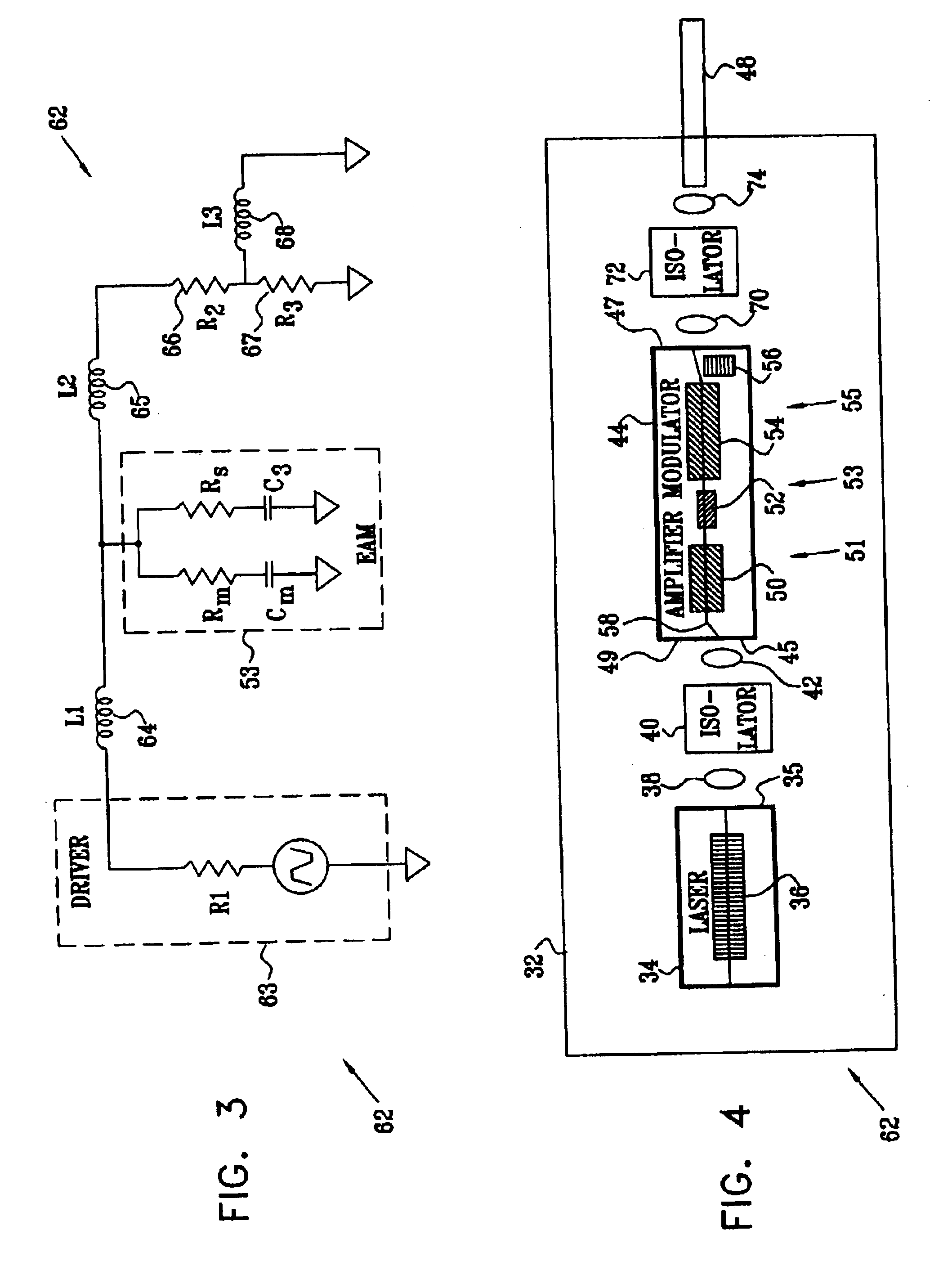
The combined SOA-EAM device is produced as a monolithic device by forming a first SOA section, an EAM section, and a second SOA section in series in a single waveguide within a semiconductor. The EAM section is coupled to an external driver using a non-capacitative matching circuit, and, most preferably, the second SOA section is operated in a partially saturated state. Forming the SOAs as two separate sections provides a number of advantages compared to using a single SOA at the input of the EAM:Output launch power of the module can be increased significantly, while the frequency response of the module remains flat, without compromising on chirp or reducing extinction ratio;Coupling loss between the SOA-EAM device and the semiconductor laser is compensated for, and coupling between the two components is more tolerant to misalignment;Total drive current to the SOAs is reduced;Heat and power dissipation of the device is improved.
In some preferred embodiments of the present invention, the hybrid module comprises a second optical isolator that is positioned between an exit facet of the combined SOA-EAM device and the fiber optic. The additional isolator minimizes optical return loss that may interfere with the performance of an external optical network.

Problems solved by technology

Other parameters that may adversely affect the output power and signal quality of the LD-EAM combination include the insertion loss (IL) of the modulator, and chirp of the EAM.
In LD-EAM transmitters known in the art the output power is limited by the power handling ability of the EAM.

Method used


Image

  • Hybrid optical transmitter with electroabsorption modulator and semiconductor optical amplifier
  • Hybrid optical transmitter with electroabsorption modulator and semiconductor optical amplifier
  • Hybrid optical transmitter with electroabsorption modulator and semiconductor optical amplifier

Examples


Embodiment Construction

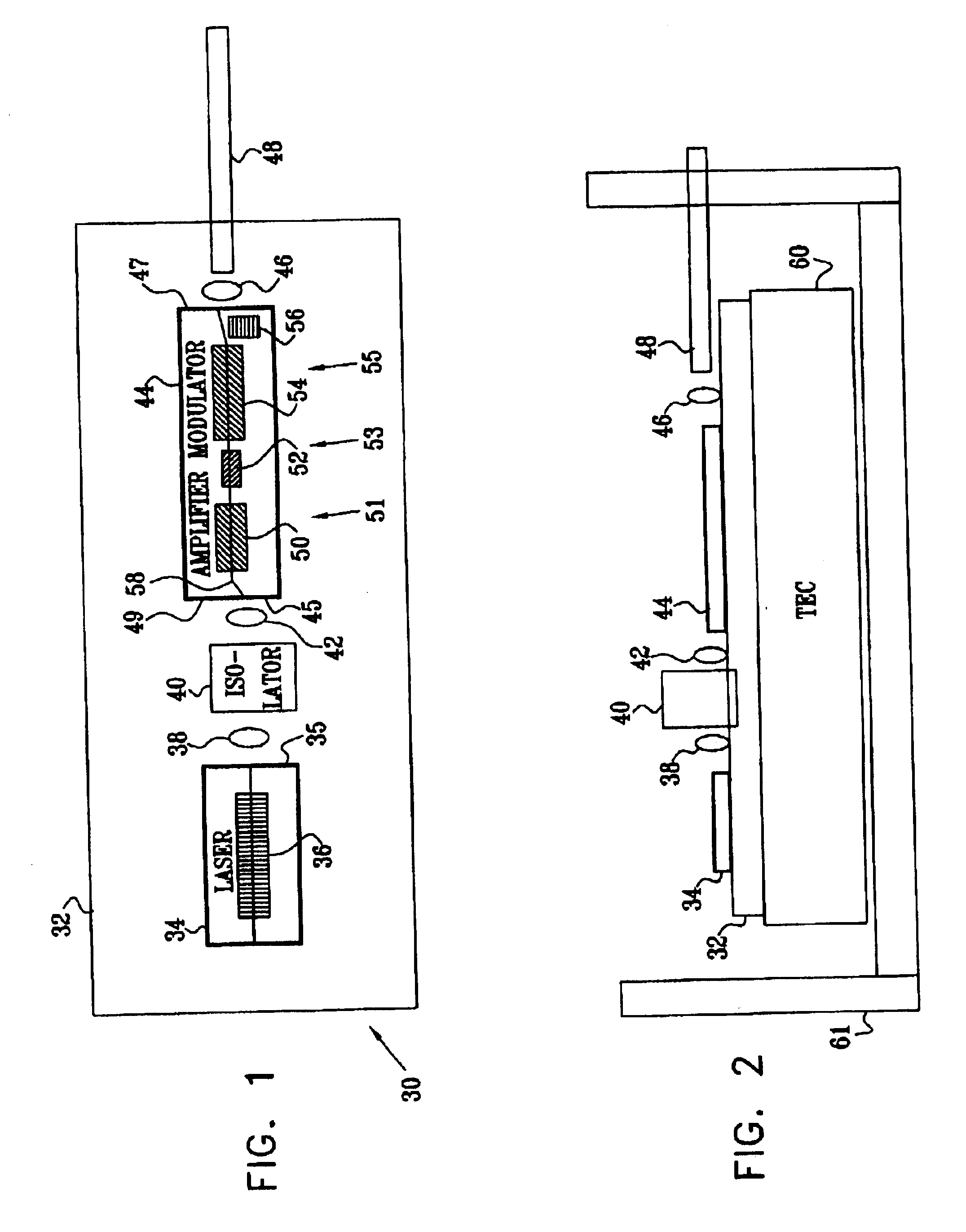
Reference is now made to FIG. 1, which is a schematic top view of a hybrid transmitter module 30, and to FIG. 2, which is a schematic side view of the module, according to a preferred embodiment of the present invention. Module 30 comprises a semiconductor laser diode (LD) 34 having a control electrode 36. Laser diode 34 may be substantially any laser diode known in the art, such as a Fabry-Perot or a distributed feedback (DFB) laser or a tunable laser such as a distributed Bragg reflector laser (DBR). LD 34 is mounted on an inert substrate 32, which acts as a ground for the laser diode. LD 34 radiates its output, typically as linearly polarized radiation, through a front facet 35.

The output from facet 35 is focussed by lenses 38 and 42 onto a front facet 45 of a combined amplifier-modulator (CAM) 44, which operates as an optical radiation amplifier. Between lenses 38 and 42 is an optical isolator 44, which acts as a substantially one-way path for the radiation from LD 34, so that t...


PUM


Abstract

An optical radiation amplifier, including an input port which receives the optical radiation and a first semiconductor optical amplifier (SOA), which is coupled to receive the optical radiation from the input port and is adapted to amplify the optical radiation to produce amplified optical radiation in response to a first current injected into the first SOA. The amplifier also includes an electro-absorption modulator (EAM), which is coupled to receive the amplified optical radiation and is adapted to modulate the amplified optical radiation in response to a modulation voltage applied to the EAM so as to produce modulated radiation. There is a second SOA, which is coupled to receive the modulated radiation and is adapted to amplify the modulated radiation in response to a second current injected into the second SOA.

Description

FIELD OF THE INVENTIONThe present invention relates generally to signal transmission, and specifically to transmission of optical signals.BACKGROUND OF THE INVENTIONAn optical signal transmitter is typically constructed from a laser followed by a modulator that modulates the coherent radiation emitted by the laser. The laser may be a laser diode (LD), and the modulator may be a semiconductor electro-absorption modulator (EAM). Typically, the LD-EAM combination is required to output a high radiation power and is also required to have a high extinction ratio (ER) and relatively flat frequency response up to the bit rate frequency.U.S. Pat. No 6,381,066 to Korn, et al., whose disclosure is incorporated herein by reference, describes an integrated semiconductor optical amplifier (SOA) system. The system consists of a single SOA which is mounted on an optical bench, with fiber optics coupling optical radiation into and out of the SOA via isolators. The system is constructed, with a diode...

Claims


Application Information

Patent Timeline
IPC IPC(8): H01S5/00H01S5/026H01S5/50H01S5/06H01S5/0683H01S5/042
CPCH01S5/5018H01S5/0064H01S5/0085H01S5/02248H01S5/02284H01S5/042H01S5/0612H01S5/0683H01S5/02415H01S5/02325H01S5/02251
Inventor KOREN, UZIELFINZI, DAVIDBIRAN, YONATAN
Owner BROADCOM INT PTE LTD
Learn More