Optical transmission line, and optical fiber and dispersion compensating module employed in the same

a technology of optical transmission lines and compensating modules, which is applied in the direction of multiplex communication, cladded optical fibres, instruments, etc., can solve the problems of not knowing that the optical transmission line has a chromatic dispersion with a small absolute value in such a broad signal wavelength band as a whole, and achieves large dispersion compensation amount, low loss, and long distance

Inactive Publication Date: 2005-03-01
SUMITOMO ELECTRIC IND LTD
View PDF28 Cites 4 Cited by
  • Summary
  • Abstract
  • Description
  • Claims
  • Application Information

AI Technical Summary

Benefits of technology

In the optical transmission line according to the present invention, the deviation of chromatic dispersion within a wavelength range of 1480 to 1620 nm is preferably 0.7 ps / nm / km or less, more preferably 0.5 ps / nm / km or less. In this case, the optical transmission line not only enables information transmission with a large capacity over a long haul, but signal light also can be collectively amplified by rear-earth doped optical fiber amplifiers (e.g., Er-or Tm-doped optical amplifier), thereby making it possible to transmit information over a longer distance.
Preferably, in the optical transmission line according to the present invention, the deviation of chromatic dispersion within a wavelength range having a width of 100 nm included in a wavelength range of 1450 to 1620 nm is 0.4 ps / nm / km or less. The dispersion-compensating optical fiber enables Raman amplification of signal light when pumping light of Raman amplification is supplied thereto. In this case, the optical transmission line not only enables information transmission with a large capacity over a long haul, but signal light also can be collectively amplified by Raman amplification when pumping light is supplied to the dispersion-compensating optical fiber, thereby making it possible to transmit information over a longer distance.
In the optical transmission line according to the present invention, the dispersion-compensating optical fiber has a chromatic dispersion of −200 ps / nm / km or more but −50 ps / nm / km or less at a wavelength of 1550 nm. Namely, the optical fiber (corresponding to the above-mentioned dispersion-compensating optical fiber) employed in the optical transmission line has a chromatic dispersion of less than zero at a wavelength of 1550 nm. Also, as characteristics at a wavelength of 1550 nm, the dispersion-compensating optical fiber has a figure of merit, defined by the ratio (|D| / L) of an absolute value of chromatic dispersion D to transmission loss L, of 200 ps / nm / km or more, and a polarization mode dispersion of 0.3 ps·km−1 / 2 or less. In this case, an optical fiber having a large dispersion compensation amount and a low loss is obtained.
Preferably, in the optical transmission line according to the present invention, the increase in transmission loss of the dispersion-compensating optical fiber resulting from OH absorption near a wavelength of 1.38 μm is 0.2 dB / km or less. Since the increase in loss resulting from OH absorption is small as such, the dispersion-compensating optical fiber is suitable for transmitting S-band signals and supplying pumping light of Raman amplification effectively.

Problems solved by technology

However, no optical transmission line having a chromatic dispersion with a small absolute value in such a broad signal wavelength band as a whole has been known.

Method used


Image

  • Optical transmission line, and optical fiber and dispersion compensating module employed in the same
  • Optical transmission line, and optical fiber and dispersion compensating module employed in the same
  • Optical transmission line, and optical fiber and dispersion compensating module employed in the same

Examples


Embodiment Construction

In the following, embodiments of the optical transmission line and the like according to the present invention will be explained in detail with reference to FIGS. 1 to 3, 4A, 4B, 5 to 9, 10A, 10B, 11 to 17, 18A, and 18B. In the explanation of the drawings, constituents identical to each other will be referred to with numerals or letters identical to each other without repeating their overlapping descriptions.

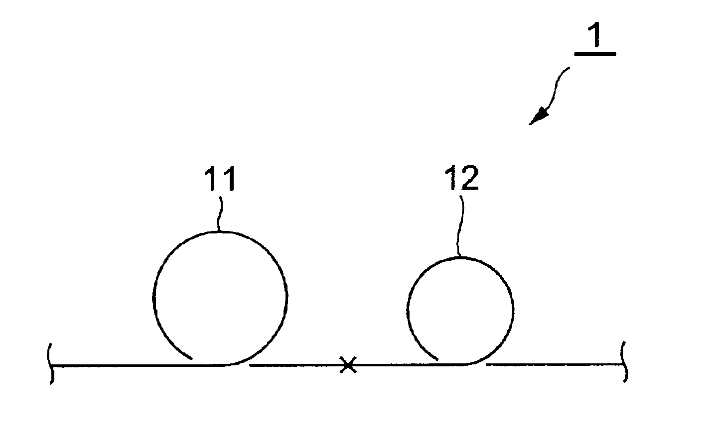
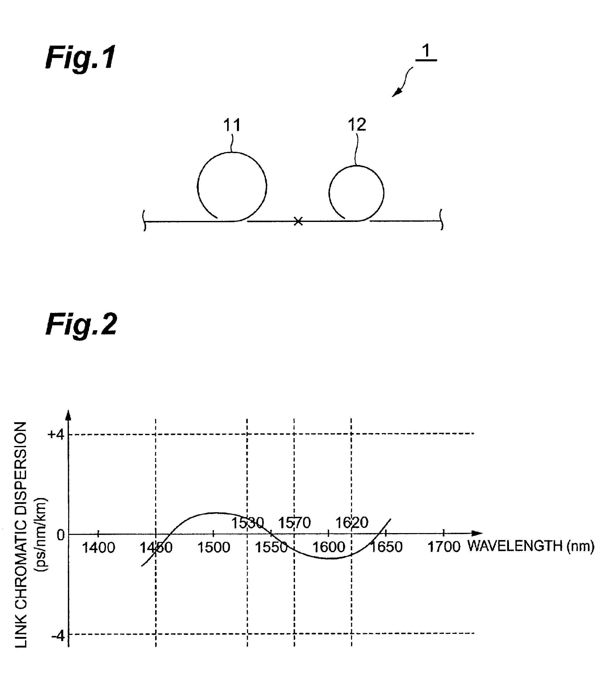
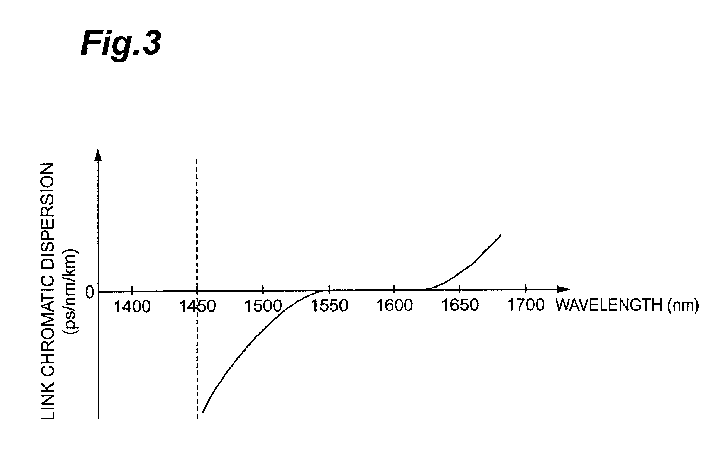
First, the schematic configuration and chromatic dispersion characteristic of the optical transmission line according to the present invention will be explained with reference to FIGS. 1 to 3. FIG. 1 is a diagram showing the schematic configuration of an optical transmission line 1 according to the present invention. FIG. 2 is a graph showing the chromatic dispersion characteristic of the optical fiber transmission line 1 according to the present invention. FIG. 3 is a graph showing the chromatic dispersion characteristic of an optical transmission line acting as a comparative e...


PUM


Abstract

The present invention relates to an optical transmission line and the like having a chromatic dispersion with a small absolute value as a whole within a signal wavelength band including S, C, and L bands. This optical transmission line comprises a single-mode optical fiber and a dispersion-compensating optical fiber which are connected to each other; and has, as characteristics of the whole optical transmission line at a wavelength of 1550 nm, a chromatic dispersion with an absolute value of 4 ps/nm/km or less, and a dispersion slope of −0.015 ps/nm2/km or more but less than 0 ps/nm2/km. Its chromatic dispersion has a maximum value within a wavelength range of 1450 to 1530 nm, and a minimum value within a wavelength range of 1570 to 1620 nm.

Description

BACKGROUND OF THE INVENTION1. Field of the InventionThe present invention relates to an optical transmission line suitable for wavelength division multiplexing (WDM) transmission systems, and an optical fiber and dispersion compensating module employable therein.2. Related Background ArtBy transmitting signal light of multiple wavelengths of channels through an optical transmission line, WDM transmission systems make it possible to transmit / receive a large capacity of information. As a signal wavelength band utilized in such a WDM transmission system, C band (1530 nm to 1565 nm) has conventionally been in use, whereas signal light in the wavelength band of L band (1565 nm to 1625 nm) has recently come into use in response to a demand for a larger capacity.In the optical transmission line as a whole, on the other hand, the optical pulse of signal light will broaden remarkably if the absolute value of chromatic dispersion is large. As a consequence, repeating sections are required to ...

Claims


Application Information

Patent Timeline
Patent Type & Authority Patents(United States)
IPC IPC(8): G02B6/34H04B10/18H04B10/2525
CPCG02B6/03666G02B6/03688G02B6/29377H04B10/2525G02B6/02233G02B6/02261G02B6/02285G02B6/02271H04B2210/258
Inventor HIRANO, MASAAKITADA, AKIRAKATO, TAKATOSHI
Owner SUMITOMO ELECTRIC IND LTD
Why Eureka
Try Eureka