Process to reduce mercury emission

a technology of mercury emission and process, applied in the field of process and, can solve the problems of nitrogen oxides being the subject of growing concern, air pollution produced by combustion systems, etc., and achieve the effects of reducing nitrogen oxide and mercury emissions, reducing carbon in fly ash, and enhancing unburned carbon

Inactive Publication Date: 2005-03-08
GENERAL ELECTRIC CO
View PDF21 Cites 23 Cited by
  • Summary
  • Abstract
  • Description
  • Claims
  • Application Information

AI Technical Summary

Benefits of technology

In an embodiment, the method decreases emissions of nitrogen oxide and mercury while decreasing carbon in fly ash. The method comprises selecting a combination of factors from the group consisting of fuel type, fuel/air staging and a combustion condition to control a combustion process to generate a flue gas comprising fly ash with enhanced unburned carbon; controlling the combustion process according to the factors to produce the flue gas comp

Problems solved by technology

Production of air pollution by combustion systems is a major problem of modern industrial society.
The nitrogen oxides are the s

Method used


Image

  • Process to reduce mercury emission
  • Process to reduce mercury emission
  • Process to reduce mercury emission

Examples


example 1

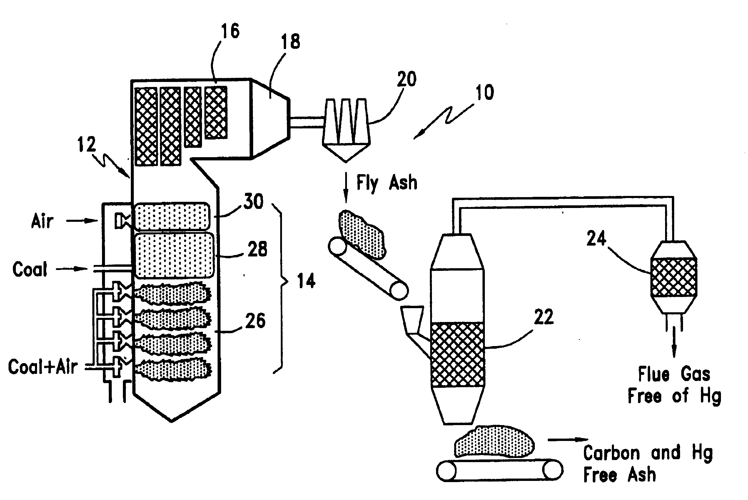
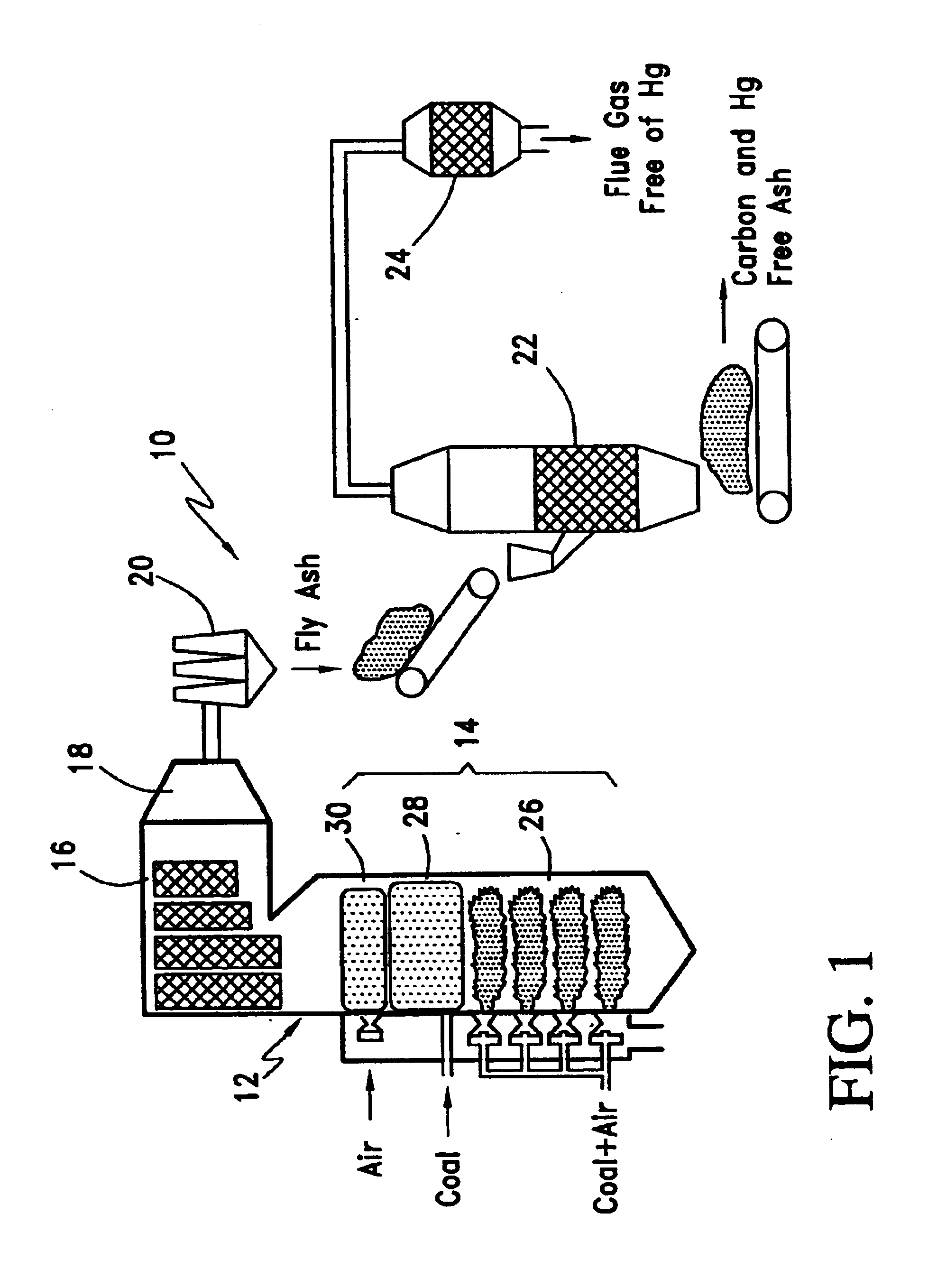
Tests were performed in a Boiler Simulator Furnace (BSF). The BSF was a down-fired combustion research facility that had a nominal firing capacity of 1×10⁶ Btu / hr. The BSF was designed to simulate chemical and thermal characteristics of a utility boiler. The BSF was equipped to fire natural gas, oil or coal. The BSF had two main sections: a vertical down-fired radiant furnace and a horizontal convective pass. The furnace was constructed of eight modular refractory lined sections with access ports. It was cylindrical in shape and had an inside diameter of 22 in. The convective pass contained air-cooled tube bundles to simulate boiler heat transfer banks. The BSF was equipped with both a baghouse and an electrostatic precipitator for particulate control at the end of the convective pass.

The BSF is well-suited to process development studies leading to utility boiler applications because it accurately simulates boiler thermal environments. Flame characteristics, gas-phase sampling, gas ...

example 2

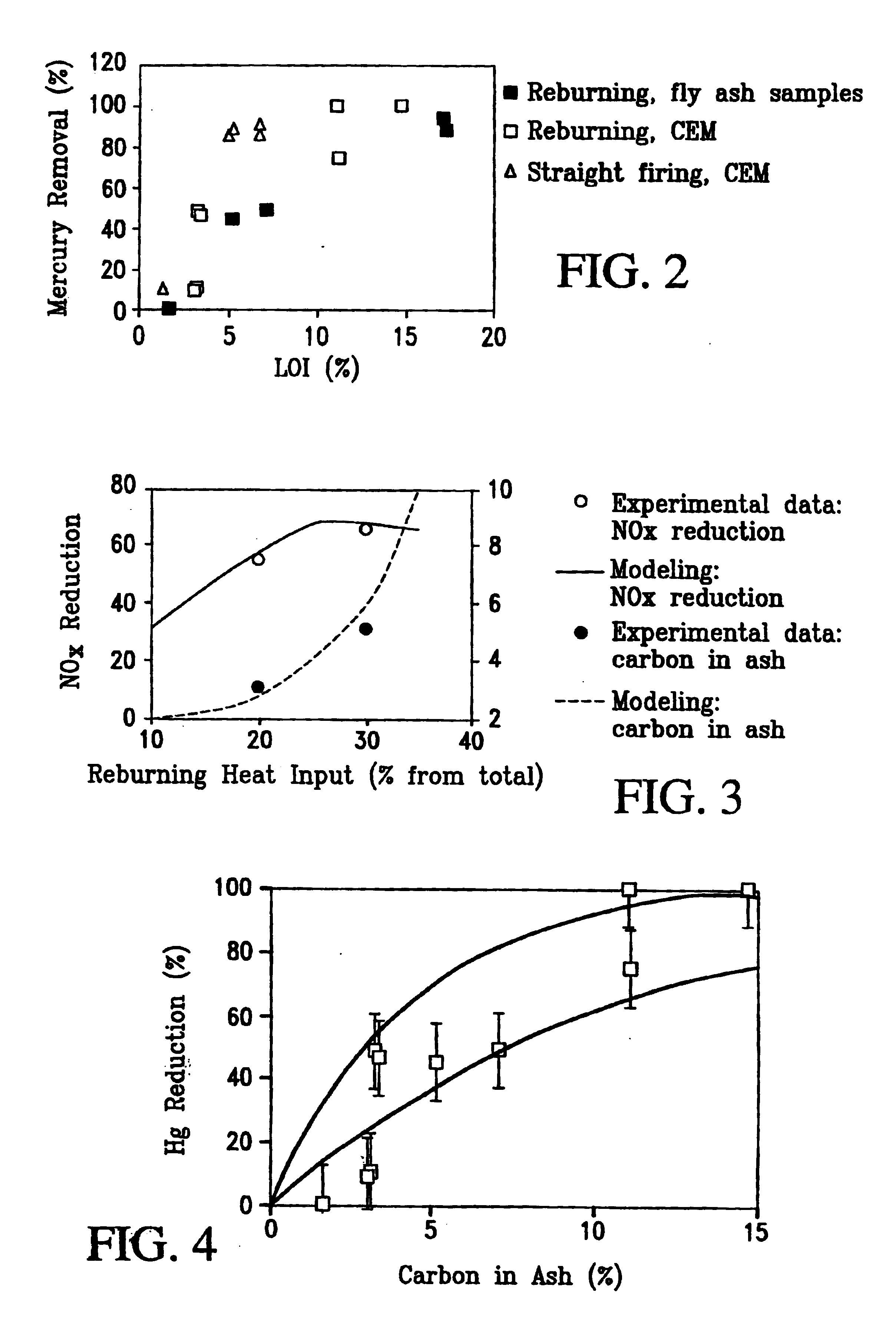
A process model was developed and used to predict NOx and mercury control in coal reburning. The process model included a detailed kinetic mechanism of coal reburning combined with gas dynamic parameters characterizing mixing of reagents and global reactions of carbon burnout and mercury absorption. In the modeling, a set of homogeneous and heterogeneous reactions representing the interaction of reactive species was assembled. Each reaction was assigned a certain rate constant and heat release or heat loss parameter. Numerical solution of differential equations for time-dependent concentrations of the reagents permitted prediction of concentration-time curves for all reacting species under selected process conditions. Modeling revealed the process conditions required for improvements in NOx and mercury removal.

The chemical kinetic code ODF, for “One Dimensional Flame” was employed to model BSF experimental data. ODF is designed to march through a series of well-stirred or plug flow ...


PUM

PropertyMeasurementUnit
Temperatureaaaaaaaaaa

Abstract

In a method to decrease emission of mercury, a factor is selected to control a combustion process to generate a flue gas comprising fly ash with enhanced unburned carbon; the combustion process is controlled according to a factor selected from reburning fuel, flue gas temperature, OFA injection, coal particle size, LNB flow, LNB design, combustion zone air, stoichiometric ratio of fuel, fuel/air mixing in a primary combustion zone and fuel/air mixing in a secondary combustion zone to produce the flue gas comprising fly ash with enhanced unburned carbon and to vaporize mercury; and the flue gas is allowed to cool to collect fly ash with enhanced unburned carbon with absorbed mercury. A system to decrease emission of mercury; comprises a combustion zone that is controlled to generate a flue gas comprising fly ash with enhanced unburned carbon and that produces vaporized mercury; and a post combustion zone to cool the flue gas to collect fly ash with enhanced unburned carbon with absorbed mercury.

Description

BACKGROUND OF THE INVENTIONThe invention relates to a process and system to reduce emissions of nitrogen oxides and mercury and to reduce the level of carbon in combustion fly ash. More specifically, the present invention provides a process and system to increase use of fly ash and to decrease nitrogen oxides and mercury from flue gases from combustion systems such as boilers, furnaces and incinerators.Production of air pollution by combustion systems is a major problem of modern industrial society. The pollution can include particulates such as fine fly ash particles from solid fuel combustion (for example, pulverized coal firing), and gas-phase species, such as oxides of sulfur (SOx, principally SO2 and SO3), carbon monoxide, volatile hydrocarbons, nitrogen oxides (mainly NO and NO2 collectively referred to “NOx”) and volatile metals such as mercury (Hg).The nitrogen oxides are the subject of growing concern because of their toxicity and their role as precursors in acid rain and p...

Claims


Application Information

Patent Timeline
IPC IPC(8): B01D53/64B01D53/46
CPCB01D53/64
Inventor LANIER, WILLIAM STEVENBOOTH, CHARLES M.LISSIANSKI, VITALI V.ZAMANSKY, VLADIMIR M.MALY, PETER M.SEEKER, WILLIAM RANDALL
Owner GENERAL ELECTRIC CO
Why Eureka
Try Eureka