Composite foam made from polymer microspheres reinforced with long fibers

a technology of polymer microspheres and composite foams, applied in the field of fiber-reinforced foams, can solve the problems of reducing the density of syntactic foams, affecting the strength of composite foams, and reducing the strength of epoxy-based syntactic foams, so as to improve the strength and modulus of composite foams, improve the strength and modulus of shear strength and modulus, and improve the effect of strain energy density and damage toleran

Inactive Publication Date: 2005-03-08
UNIV OF SOUTHERN CALIFORNIA
View PDF20 Cites 60 Cited by
  • Summary
  • Abstract
  • Description
  • Claims
  • Application Information

AI Technical Summary

Benefits of technology

The invention provides a composite foam comprising expandable microspheres reinforced with fibers. In one aspect of the invention, the composite foam of the invention is fabricated by infiltrating low-density fiber with microspheres. The combination is then heated to expand the foam. The resulting composite foam comprises about 10 wt % fibers (e.g., aramid fibers) and has a density of about 100 kg/m3. Mechanical properties, crack propagation, and microstructure of the com

Problems solved by technology

However, because the microspheres are hollow, their inclusion reduces the density of the syntactic foam.
Although one- and two-part epoxy-based syntactic foams have enjoyed some success as reinforcing foam in the auto industry, they suffe

Method used


Image

  • Composite foam made from polymer microspheres reinforced with long fibers
  • Composite foam made from polymer microspheres reinforced with long fibers
  • Composite foam made from polymer microspheres reinforced with long fibers

Examples


example 1

Polyvinyl Chloride (PVC)-Fiber Composites

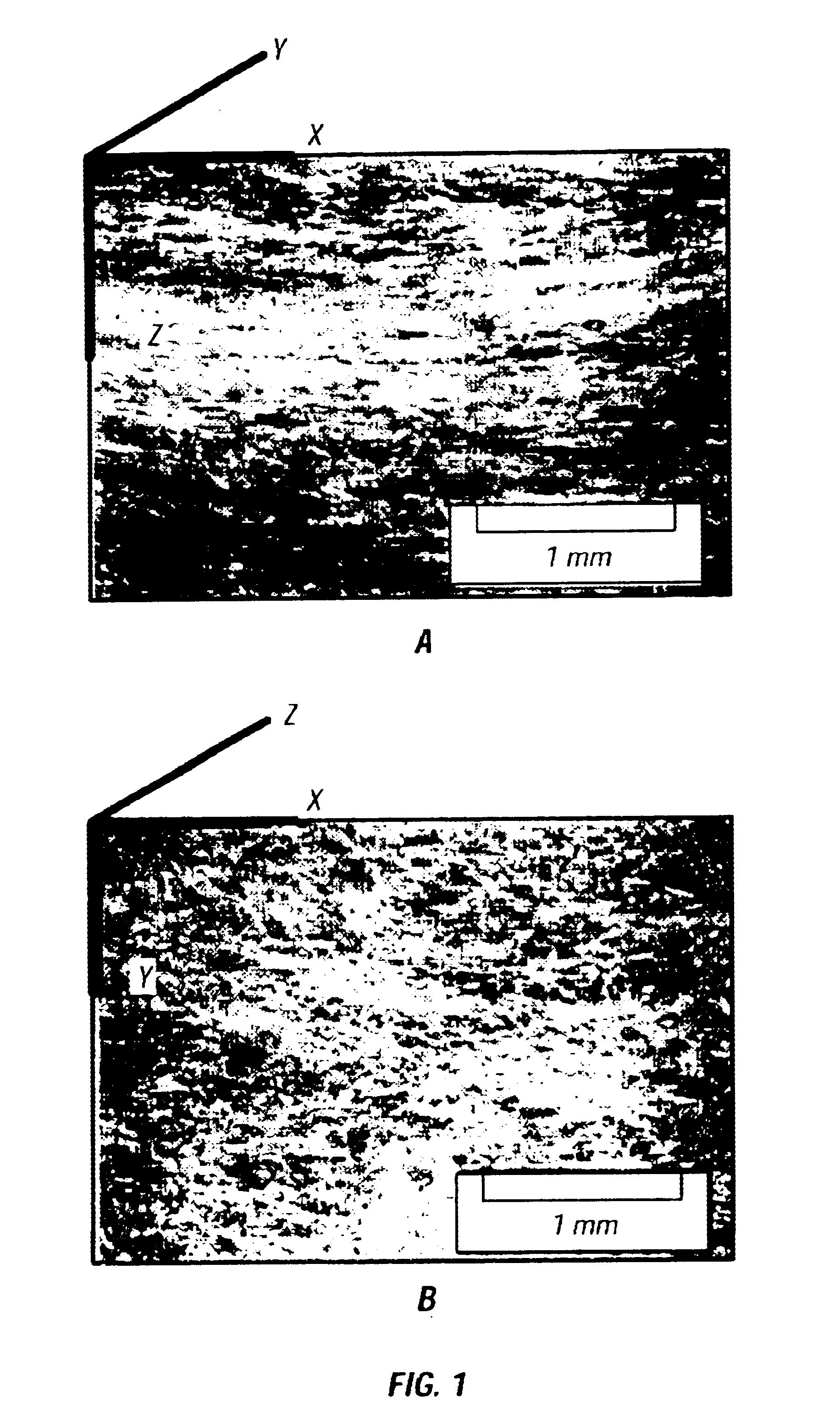
A non-woven aramid fiber webbing was selected for the preform. This product (supplied by Tex Tech Industries, Inc.) is produced via a dry laid carding process without needle punching. A brief description of the webbing structure is given here, and details of the carding process are provided by the manufacturer. The product is a unidirectional, light weight webbing sheet that is subsequently stacked to produce a permeable fiber preform with loft. Layers can also be cross-lapped to form bi-directional webbing.

The webbing used was comprised of chopped aramid fibers (Kevlar® 29), 75 mm long. FIG. 1 illustrates the fiber arrangement of the unidirectional webbing. The webbing pre-form has a layered structure. Fibers extend primarily in one direction (X), although there is some waviness within the layers. A degree of fiber crossover between layers holds the preform together. Most of the composite foam samples were reinforced with this unidirectional...

example 2

Polyacrylonitrile (PAN)-Fiber Composites

Several types of fiber preforms were selected for evaluation. The preforms consisted of random, 3D arrangements of fibers, much like wool or cotton. Composite foams were synthesized using 30 wt % polyester fibers, 8 wt % aramid fibers, and 8 wt % glass fibers. Unreinforced foam was also synthesized and tested for comparison. The polyester fiber preform (commercially available as “NU-Foam”) consisted of fibers with an average length of ˜50 mm. Aramid and glass preforms were fabricated from Kevlar® 49 and E-glass fibers, respectively (with average lengths ˜100 mm). Properties of the fibers are shown in Table 6.

TABLE 6Properties of reinforcing fibersTensileTensileDensitymodulusstrengthg / cm3GPaGPaKevlar ® 491.441313.8E - Glass2.55723.5Polyester1.385.10.32

Expandable microspheres based on thermoplastic polyacrylonitrile (PAN) were obtained from Expancel, Inc. and were used for preparation of the basic foam material. Each hollow microsphere consisted...


PUM

PropertyMeasurementUnit
Percent by massaaaaaaaaaa
Fractionaaaaaaaaaa

Abstract

Composite foam based on expandable microspheres reinforced with fibers is described. Also disclosed are methods of making microsphere foam reinforced with fibers and methods of use thereof. The disclosure provides foam that performs equally and better than the performance of most thermoplastic foams commercially available.

Description

TECHNICAL FIELDThis invention relates to foam, and more particularly to fiber-reinforced foams.BACKGROUNDThe properties of rigid polymer foams are important for the design and performance of sandwich structures that are used in a wide range of engineering applications, including airframes, transportation vehicles, boat hulls, radar systems, surf boards, and space structures (DIAB Inc. Technical Information for Divinycell® Foam, 2002; Rohm A G. Technical Information for Rohacell® Foam, 2002; Baltek Corp. Technical Information, 2002; Marsh J. Fire-Safe Composites for Mass Transit Vehicles. Reinforced Plastics, 46(9):26-30, 2002). Currently, most high-performance structural foams are fabricated by expanding (blowing) liquid polymers to form rigid, low-density foams. Some of the leading thermoplastic foams made in this way are polymethacrylimide (PMI) and partly cross-linked polyvinyl chloride (PVC), with trade names Rohacell® and Divinycell®.Syntactic foams are composites consisting of...

Claims


Application Information

Patent Timeline
IPC IPC(8): B29C70/02B29C70/00B29C70/66C08J9/00C08J9/32
CPCB29C70/025C08J9/32C08J9/0085B29C70/66
Inventor NUTT, STEVEN R.VAIKHANSKI, LEV
Owner UNIV OF SOUTHERN CALIFORNIA
Why Eureka
Try Eureka