Electrical insulators, materials and equipment

Inactive Publication Date: 2005-03-08
TYCO ELECTRONICS RAYCHEM GMBH
View PDF9 Cites 19 Cited by
  • Summary
  • Abstract
  • Description
  • Claims
  • Application Information

AI Technical Summary

Benefits of technology

Furthermore, a capacitive stress grading effect may be achieved by alternating bands of the stress control material with exposed underlying bands of the insulating material.
An insulator in accordance with the present invention would be expected

Problems solved by technology

The electrical stress between the insulator electrodes results in leakage current flowing over the surface of the in

Method used


Image

  • Electrical insulators, materials and equipment
  • Electrical insulators, materials and equipment
  • Electrical insulators, materials and equipment

Examples


Embodiment Construction

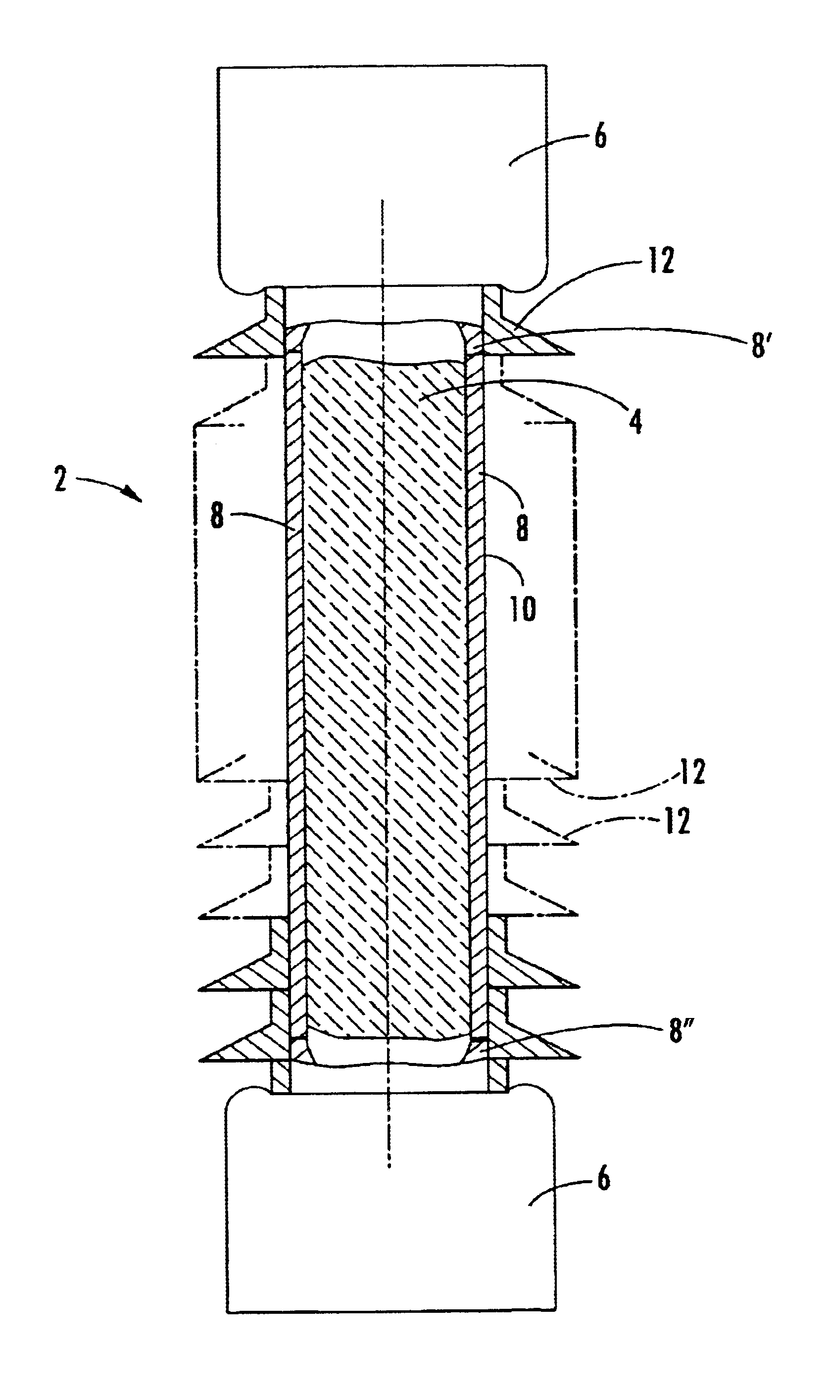
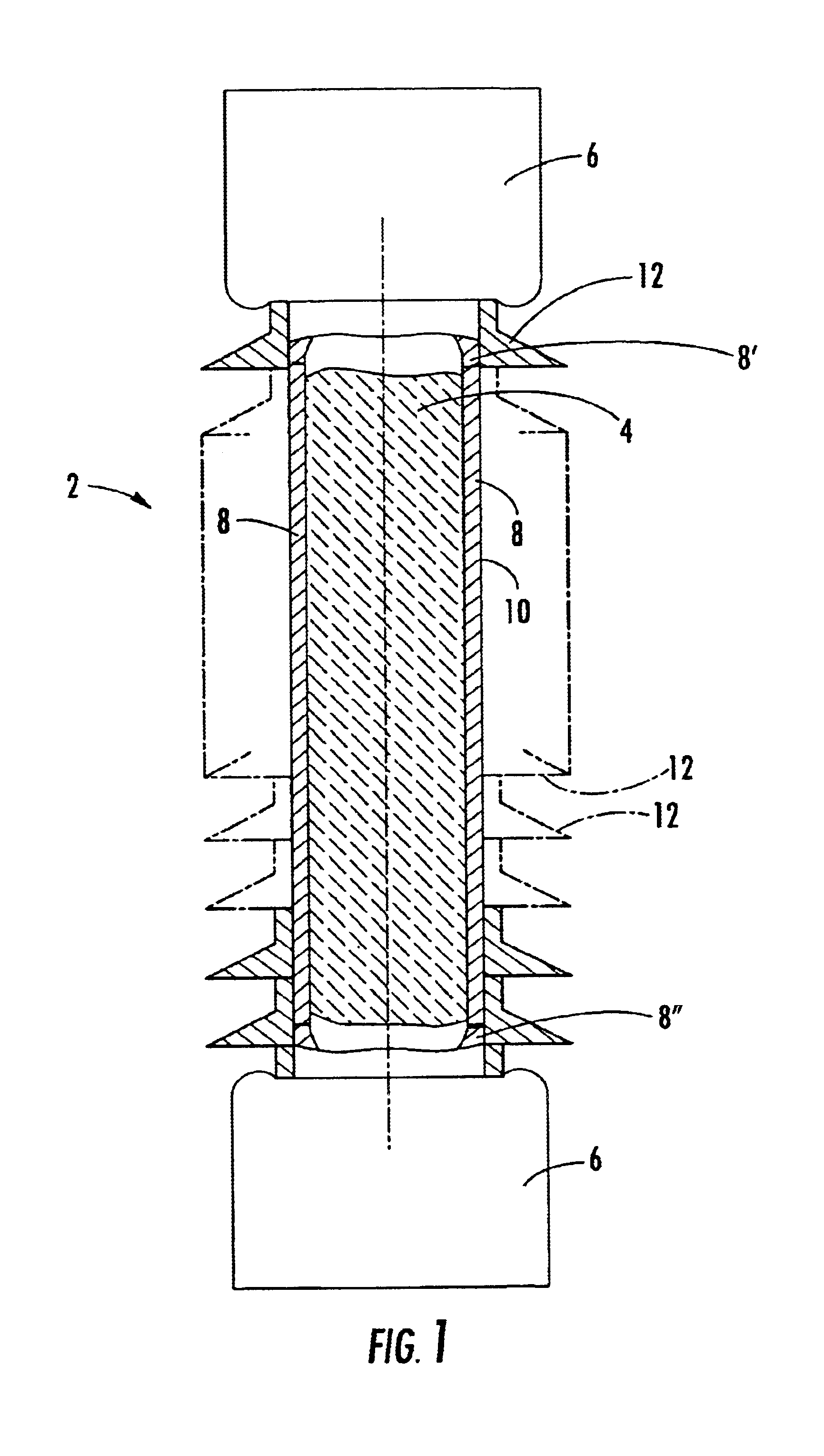
Referring to FIG. 1, an insulator 2 comprises a cylindrical tubular core 4 of ceramic material, having a brass electrode 6 mounted on each end thereof. A layer of doped zinc oxide varistor material 8 is moulded on to the entire outer surface of the insulating core 4 between the electrodes 6. An optional outer protection layer 10 is applied to cover the entire outer surface of the stress-controlling layer 8. The protection layer 10 is provided with a pluraity of generally circular sheds 12 that project radially of the insulator 2. Core 4 may alternatively be a solid body.

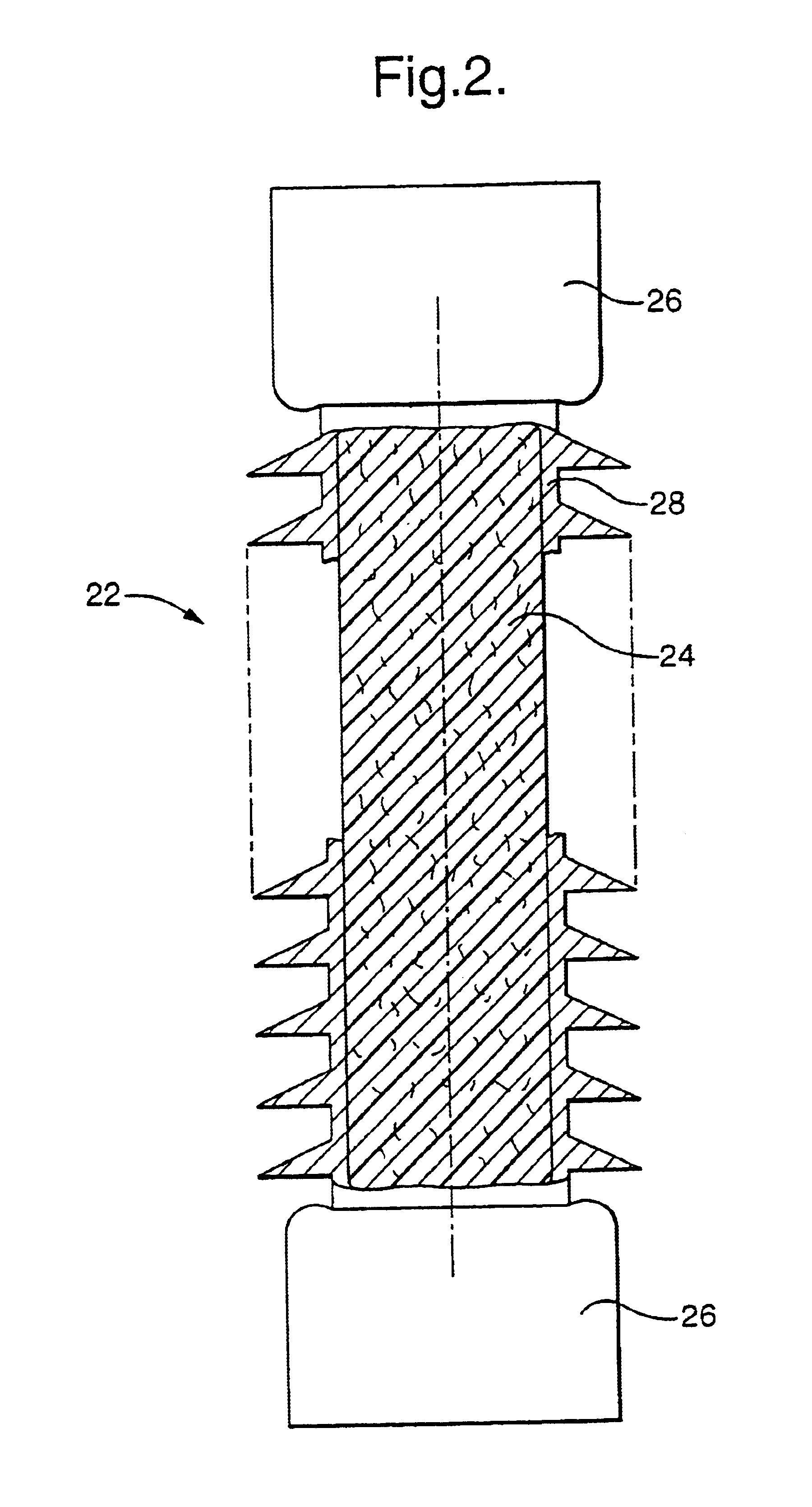
Referring to FIG. 2, the insulator 22 comprises an inner cylindrical core 24 of fiber-reinforced epoxy resin extending between a pair of terminal electrodes 26. In this embodiment, however, a single, shedded outer component 28 is moulded onto the core 24. The component 28 is formed of a material that performs the function of controlling the stress on the outer surface of the insulator 24 as well as providing outer en...


PUM


Abstract

An elongate high voltage insulator is formed of a rod or tube of insulating material, with a pair of electrodes spaced apart longitudinally thereof. At least part, and preferably the whole of the outer surface of the insulating material is covered by a layer of material including a particulate filler of varistor powder in a matrix having a switching electrical stress-controlling characteristic that is in electrical contact with each of the electrodes. The insulator core may be made of porcelain, and the stress-controlling material may be zinc oxide.

Description

FIELD OF THE INVENTIONThis invention relates to electrical insulators, material, and equipment, for example an elongated high votage insulator.BACKGROUND OF THE INVENTIONAn insulator typically comprises an insulating core that extends between two electrodes which, in operation, are maintained at significantly different electrical potentials, one of which may be earth. The insulating core may comprise a tube or a rod, which may be made of a ceramic material or of glass fiber reinforced plastics material, for example. Typically in an electrical distribution system, one end of the insulator is maintained at earth potential, and the other end is at the potential of the system, which may be 10 kV or above, for example the 375 kV electricity distribution system of the UK. At high voltages, the insulator serves to isolate the system from earth, and the higher the operating voltage of the system, the longer the insulator has to be in order to maintain the isolation. The electrical stress be...

Claims


Application Information

Patent Timeline
IPC IPC(8): H01C7/102H01B17/00H01B17/42H01B7/00H01B17/26H01B17/50
CPCH01B17/005H01C7/102H01B17/42H01B17/02
Inventor BOETTCHER, BODOLIETZKE, RALFMALIN, GEROLDGLEMBOCKI, ROBERT PAULSPALDING, MATTHEW HELM
Owner TYCO ELECTRONICS RAYCHEM GMBH
Why Eureka
Try Eureka