Multiaxis turbine

a turbine and multi-axis technology, applied in the direction of renewable energy generation, electric generator control, greenhouse gas reduction, etc., can solve the problems of increasing the cost of other items in the turbine other than the blades, increasing the stress on the rotors, and high cost of large rotors, so as to achieve the effect of more durabl

Inactive Publication Date: 2005-03-08
RICKER JONATHAN C
View PDF15 Cites 35 Cited by
  • Summary
  • Abstract
  • Description
  • Claims
  • Application Information

AI Technical Summary

Benefits of technology

The primary object of the invention is to provide more durable blades by resolving cyclical stress problems in vertical axis wind turbines.

Problems solved by technology

Unfortunately, the large rotors are expensive because the stress on the rotors increase dramatically as the diameter increases.
This increase in the diameter of blades for producing substantial power can increase the cost of other items in the turbine other than the blades.
Large blades which have not been properly produced can create structural stress and fatigue problems for the gearbox, tower, and the system that turns the generator toward the optimal wind direction.
In the past, wind turbines were supported by a single tower and guy wires in many cases leading to many vibration and frequency related problems.
The blades of vertical axis turbines were large and could be limited in the design and the materials used.
Due to the large size of the fiberglass blades, the strength was limited in order to bend the blade at the place of installation.
The blades had to be made of significant length and the available extrusion equipment is not available.
However, the fatigue factor in blades using those material suffered from structural stress caused by cyclical loads on vertical blades.
The construction and installation was complex and costly.
The vertical blades in prior technology could not place the rotor high enough above the ground in order to a turbulence leading to long term structural problems
The designing of one blade per shaft section was expensive and had imbalance problem in past turbines there were numerous attempts toward developing a horizontal one bladed turbine.
However, it was not seriously commercialized.

Method used


Image

  • Multiaxis turbine
  • Multiaxis turbine
  • Multiaxis turbine

Examples


Embodiment Construction

Detailed descriptions of the preferred embodiment are provided herein. It is to be understood, however, that the present invention may be embodied in various forms. Therefore, specific details disclosed herein are not to be interpreted as limiting, but rather as a basis for the claims and as a representative basis for teaching one skilled in the art to employ the present invention in virtually any appropriately detailed system, structure or manner.

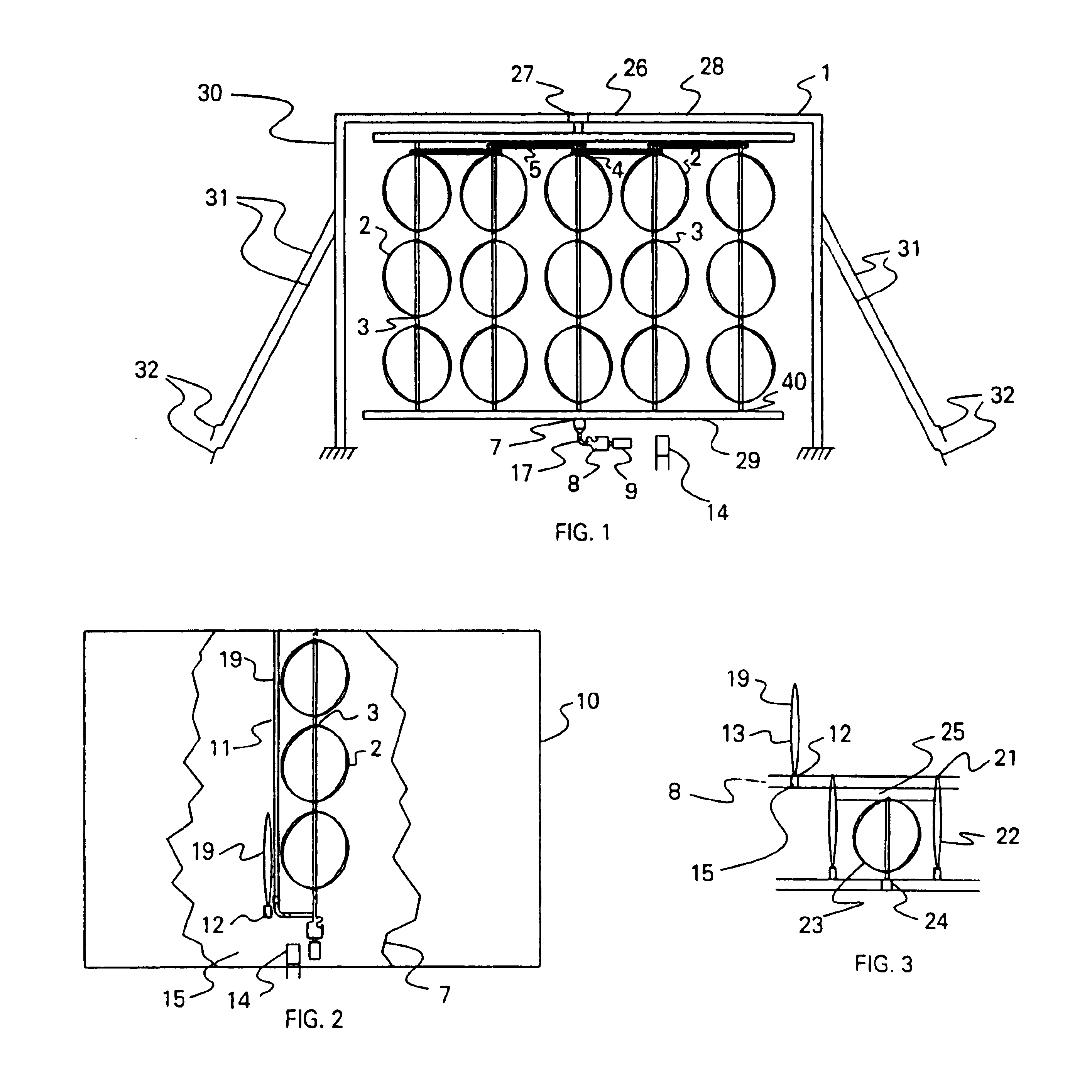
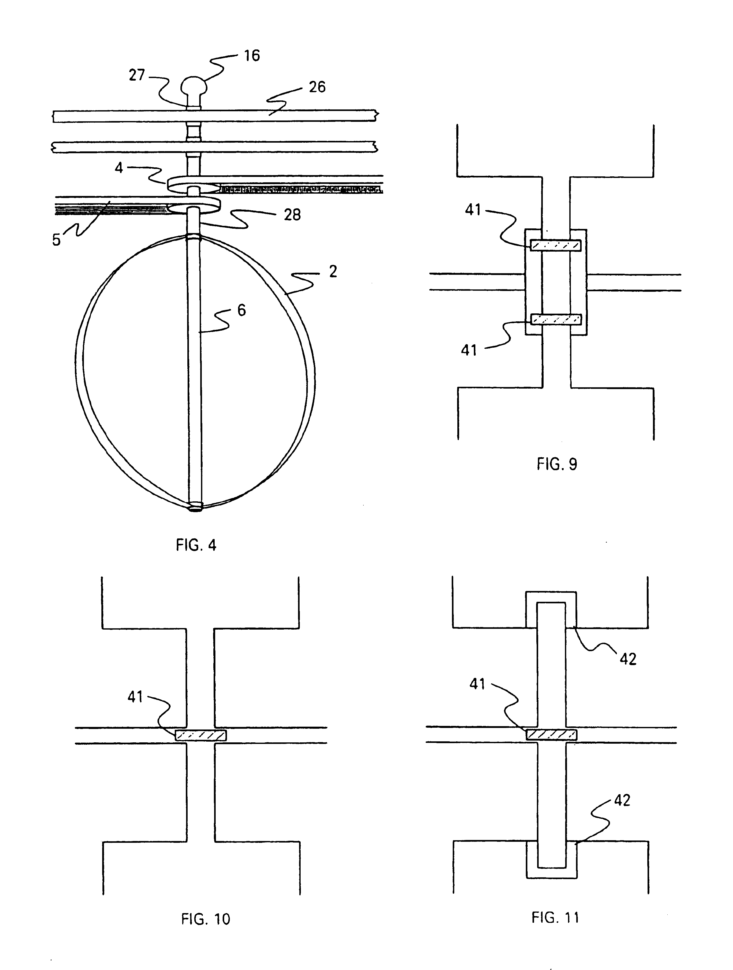
In the preferred embodiment, a Multi axis Turbine comprising a roof or an external upper covering (not shown) has a tower structure using a plurality of elongated member or steel square tubing 1104. The said members are connected to each other with supporting horizontal members or steel tubing 1104. The square tubing or horizontal elongated members are connected to the rotation means or shafts with a bearing. A plurality or several impact impellers also referred to as blades are connected to the shaft. The several blades along each shaft a...


PUM


Abstract

Multiaxis Turbine with an external upper covering, a tower structure with a plurality of vertical elongated members connected to each other with supporting horizontal elongated members, and a plurality of smaller blades on a rotation connected to a tower structure with a plurality of the rotation. A preferred embodiment includes impact impellers connected to a rotation creating a swept area with a height to diameter ratio of greater than four. A preferred embodiment includes wherein said impact impellers connected to a rotation means creating a swept area with a height to diameter ratio of greater than ten.

Description

BACKGROUND OF THE INVENTIONThis invention relates generally to the field of wind energy, and more particularly to vertical axis turbines and Turbines with more than one axis or shaft.Wind turbines utilize a rotor for converting the energy of the air stream into rotary mechanical power as a power conversion device from the wind. Wind machines can take advantage of a free and inexhaustible power source of mechanical power for various purposes including driving an electrical generator. Most wind turbines are the horizontal-axis wind turbine (HAWT). However, many wind turbines are known as vertical-axis turbines (VAWT). The blades of a VAWT are arranged vertically. VAWTs has design advantages including the generator being on the ground level for easier maintenance and avoiding the need to change the blade direction every time the wind changes directions. The most related wind turbines to the invention are the vertical axis turbines VAWT including turbines using Darrieus related technolo...

Claims


Application Information

Patent Timeline
Patent Type & Authority Patents(United States)
IPC IPC(8): F03D3/00
CPCF03D3/00F05B2240/40Y02B10/30Y02E10/74Y02E10/728F03D3/02
Inventor RICKER, JONATHAN C
Owner RICKER JONATHAN C
Why Eureka
Try Eureka