Timing control for two-chamber gas discharge laser system

a gas discharge laser and time control technology, applied in the direction of instruments, photomechanical equipment, active medium materials, etc., can solve the problems of adversely affecting wavelength and/or bandwidth, affecting the quality of laser beams, and affecting the stability of laser beams. the effect of reducing the cost of operation, bandwidth, and improving the control of wavelength

Inactive Publication Date: 2005-03-08
CYMER INC
View PDF44 Cites 51 Cited by
  • Summary
  • Abstract
  • Description
  • Claims
  • Application Information

AI Technical Summary

Benefits of technology

The present invention provides feedback timing control equipment and process for an injection seeded modular gas discharge laser. A preferred embodiment is a system capable of producing high quality pulsed laser beams at pulse rates of about 4,000 Hz or greater and at pulse energies of about 5 to 10 mJ or greater for integrated outputs of about 20 to 40 Watts or greater. The feedback timing control is programmed to permit in some circumstances discharges timed so that no significant laser energy is output from the system. Use of this technique permits burst mode operation in which the first discharge of a burst is a no-output discharge so that timing parameters for each of the two chambers can be monitored before the first laser output pulse of the burst. Two separate discharge chambers are provided, one of which is a part of a master oscillator producing a very narrow band seed beam which is amplified in the second discharge chamber. The chambers can be controlled separately permitting optimization of wavelength parameters in the master oscillator and optimization of pulse energy parameters in the amplifying chamber. A preferred embodiment is an ArF excimer laser system configured as a MOPA and specifically designed for use as a light source for integrated circuit lithography. In this preferred embodiment, both of the chambers and the laser optics are mounted on a vertical optical table within a laser enclosure. In the preferred MOPA embodiment, each chamber comprises a single tangential fan providing sufficient gas flow to permit operation at pulse rates of 4000 Hz or greater by clearing debris from the discharge region in less time than the approximately 0.25 milliseconds between pulses. The master oscillator is equipped with a line narrowing package having a very fast tuning mirror capable of controlling centerline wavelength on a pulse-to-pulse basis at repetition rates of 4000 Hz or greater and providing a bandwidth of less than 0.2 pm (FWHM). This preferred embodiment also includes a pulse multiplying module dividing each pulse from the power amplifier into either two or four pulses in order to reduce substantially deterioration rates of lithography optics. Other preferred embodiments are configured as KrF or F2 MOPA laser systems.

Problems solved by technology

These excimer lasers, when used for integrated circuit lithography, are typically operated in an integrated circuit fabrication line “around-the-clock” producing many thousands of valuable integrated circuits per hour; therefore, down-time can be very expensive.
Some improvements can be provided with the basic design as described in the '884 patent; however, major improvements with that basic design may not be feasible.
For example, with a single discharge chamber precise control of pulse energy may adversely affect wavelength and / or bandwidth and vice versa especially at very high pulse repetition rates.
Laser systems comprised of two separate systems tend to be substantially more expensive, larger and more complicated than comparable single chamber laser systems.
Therefore, commercial application of these two chamber laser systems has been limited.
Furthermore, the population inversion created by the discharge is very rapidly depleted so that the population inversion effectively exists only during the discharge.
This can be a problem because within typical pulse power systems there are several potential causes of variation in the timing of the discharges.
Thus in the prior art, timing errors can be reduced but they could not be eliminated.
This technique does not work well; however, for the first pulse following an idle period because the temperature of electrical components tend to drift during idle periods changing the timing characteristics of the components.

Method used


Image

  • Timing control for two-chamber gas discharge laser system
  • Timing control for two-chamber gas discharge laser system
  • Timing control for two-chamber gas discharge laser system

Examples


Embodiment Construction

Preferred embodiments of the present invention can be described by reference to the drawings.

Preferred Layout

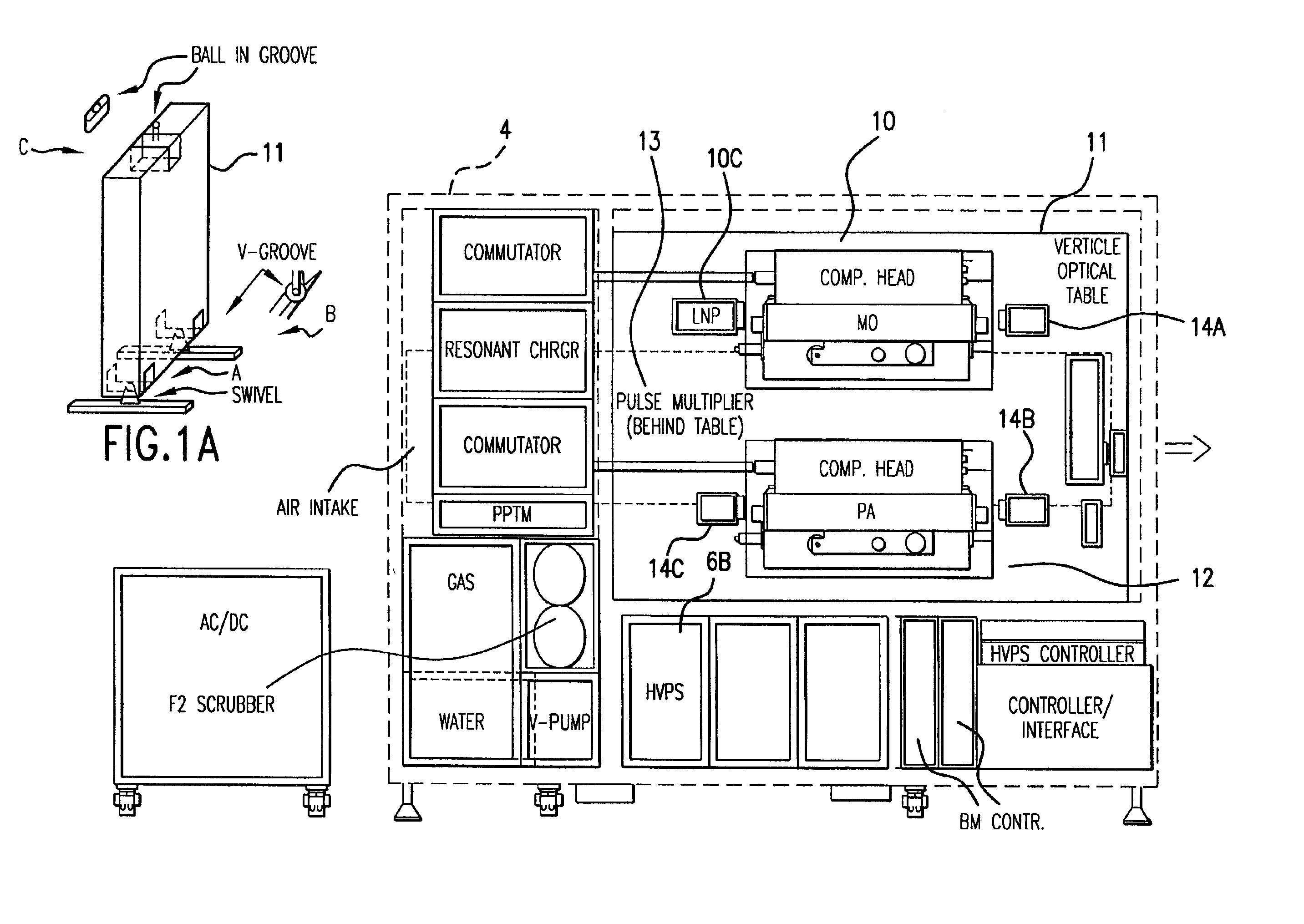
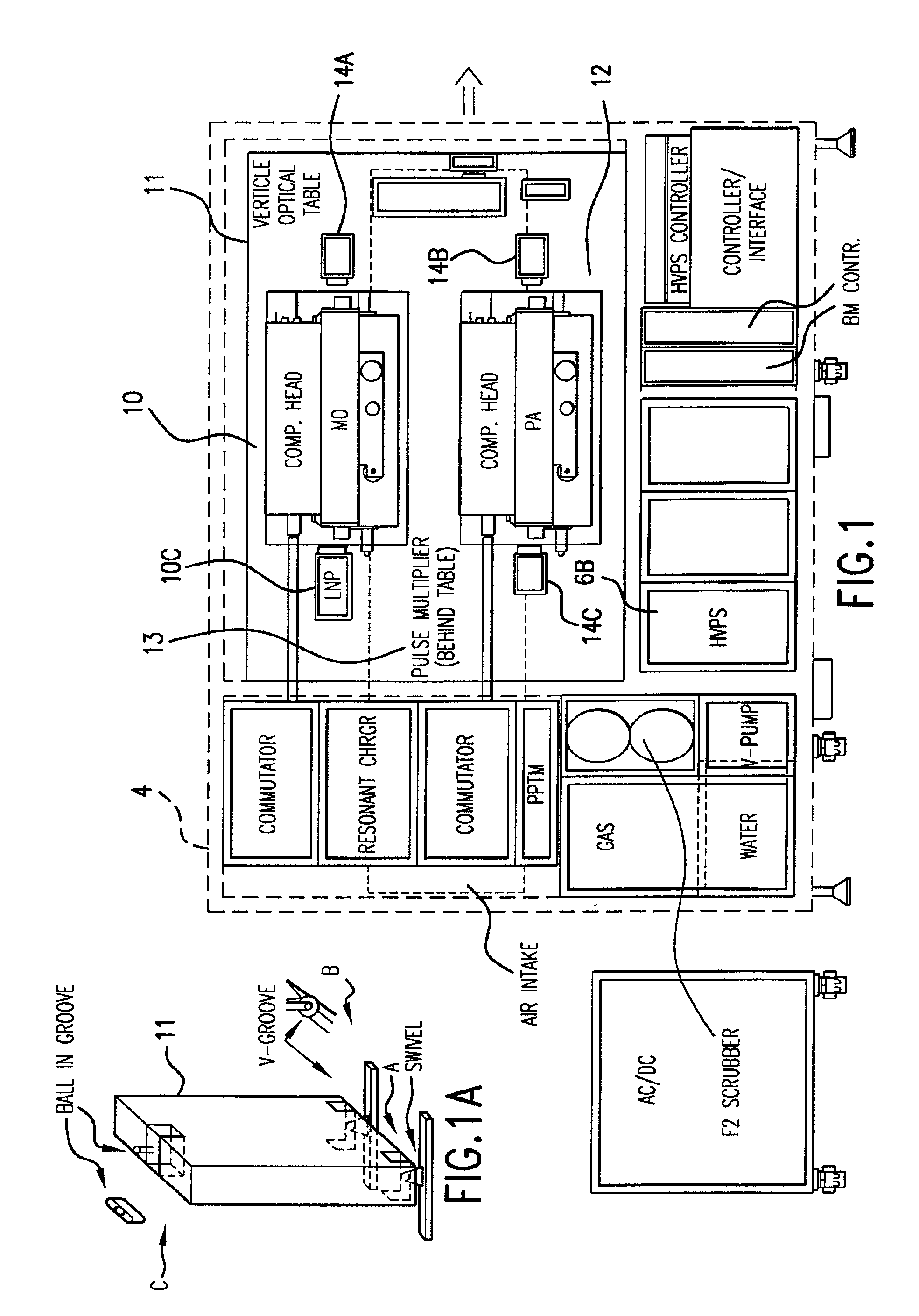
FIG. 1 is a preferred general layout of a two-chamber ArF discharge laser system configured as a master oscillator power amplifier (MOPA) system. The system includes the following features which are described in much more detail in U.S. patent application Ser. No. 10 / 012,002 filed Nov. 30, 2001. Features included are:(1) The two chambers and the laser optics are mounted on a vertical optical table 11 which is kinematically mounted within the laser cabinet 4. The chambers are supported on stiff cantilever arms bolted to the optical table. In this design the master oscillator 10 is mounted above the power amplifier 12.(2) A high voltage power supply 6B is contained within laser cabinet 4. This two chamber-ArF 4000 Hz system needs only a single 1200 volt power supply. The same is true for a 4000 Hz KrF system. The laser cabinet, however, is provided with space for two additional...


PUM

PropertyMeasurementUnit
voltagesaaaaaaaaaa
charging voltageaaaaaaaaaa
voltage electrical potentialaaaaaaaaaa

Abstract

Feedback timing control equipment and process for an injection seeded modular gas discharge laser. A preferred embodiment is a system capable of producing high quality pulsed laser beams at pulse rates of about 4,000 Hz or greater and at pulse energies of about 5 to 10 mJ or greater for integrated outputs of about 20 to 40 Watts or greater. The feedback timing control is programmed to permit in some circumstances discharges timed so that no significant laser energy is output from the system. Use of this technique permits burst mode operation in which the first discharge of a burst is a no-output discharge so that timing parameters for each of the two chambers can be monitored before the first laser output pulse of the burst. Two separate discharge chambers are provided, one of which is a part of a master oscillator producing a very narrow band seed beam which is amplified in the second discharge chamber. The chambers can be controlled separately permitting optimization of wavelength parameters in the master oscillator and optimization of pulse energy parameters in the amplifying chamber.

Description

BACKGROUND OF THE INVENTIONElectric Discharge Gas LasersElectric discharge gas lasers are well known and have been available since soon after lasers were invented in the 1960s. A high voltage discharge between two electrodes excites a laser gas to produce a gaseous gain medium. A resonance cavity containing the gain medium permits stimulated amplification of light which is then extracted from the cavity in the form of a laser beam. Many of these electric discharge gas lasers are operated in a pulse mode.Excimer LasersExcimer lasers are a particular type of electric discharge gas laser and they have been known since the mid 1970s. A description of an excimer laser, useful for integrated circuit lithography, is described in U.S. Pat. No. 5,023,884 issued Jun. 11, 1991 entitled “Compact Excimer Laser.” This patent has been assigned to Applicants'employer, and the patent is hereby incorporated herein by reference. The excimer laser described in patent '884 is a high repetition rate puls...

Claims


Application Information

Patent Timeline
Patent Type & Authority Patents(United States)
IPC IPC(8): G03F7/20H01S3/14H01S3/08H01S3/097H01S3/223H01S3/225H01S3/036H01S3/23H01S3/03H01S3/038H01S3/13H01S3/134H01S3/0971H01S3/04H01S3/22H01S3/00H01S3/139H01S3/041H01S3/102H01S3/0975H01S3/0943
CPCG03F7/70025H01S3/2366G03F7/70575H01S3/03H01S3/036H01S3/0385H01S3/08004H01S3/09705H01S3/0971H01S3/223H01S3/225G03F7/70041H01S3/0057H01S3/038H01S3/041H01S3/08009H01S3/0943H01S3/097H01S3/09702H01S3/0975H01S3/134H01S3/139H01S3/22H01S3/2207H01S3/2251H01S3/2256H01S3/2258H01S3/2308H01S3/2333
Inventor ERSHOV, ALEXANDER I.NESS, RICHARD M.
Owner CYMER INC
Why Eureka
Try Eureka