
Eye registration and astigmatism alignment control systems and method

a technology of alignment control and eye registration, applied in the field of eye registration and astigmatism alignment alignment control system and method, can solve the problems of affecting the accuracy of alignment, uncomfortable procedure for patients, and rapid loss of impression definition, so as to avoid placing patients and accurate orienting

Inactive Publication Date: 2005-03-15
ALCON INC
View PDF36 Cites 23 Cited by
  • Summary
  • Abstract
  • Description
  • Claims
  • Application Information

AI Technical Summary

Benefits of technology

A system and method are provided for accurately orienting an eye for surgery to the same orientation it had during an objective measurement. An orientation correction algorithm is provided to the software driving a corrective surgical device. Further, pairs of eye images taken at different times can be aligned (registered). The system and method also avoids placing a patient in an uncomfortable or harmful situation.
Thus this aspect of the present invention provides a system and method for achieving a precise registration of the eye with a measurement of the movement of an eye feature. As a result, the prescription measurement for reshaping the cornea will account for the rotation and translation of the eye occurring between measurements made with the patient in a sitting position and laser surgery with the patient in a prone position.

Problems solved by technology

Techniques known in the art for accommodating this movement have included marking the eye by cauterizing reference points on the eye using a cautery instrument (U.S. Pat. No. 4,476,862) or caustic substance, a very uncomfortable procedure for the patient.
However, the time delay from measurement to surgery often causes the ink to run, affecting the accuracy of an alignment.
However, the impression loses its definition quickly relative to the time period between the measurement and surgery.

Method used


Image

  • Eye registration and astigmatism alignment control systems and method
  • Eye registration and astigmatism alignment control systems and method
  • Eye registration and astigmatism alignment control systems and method

Examples


first embodiment

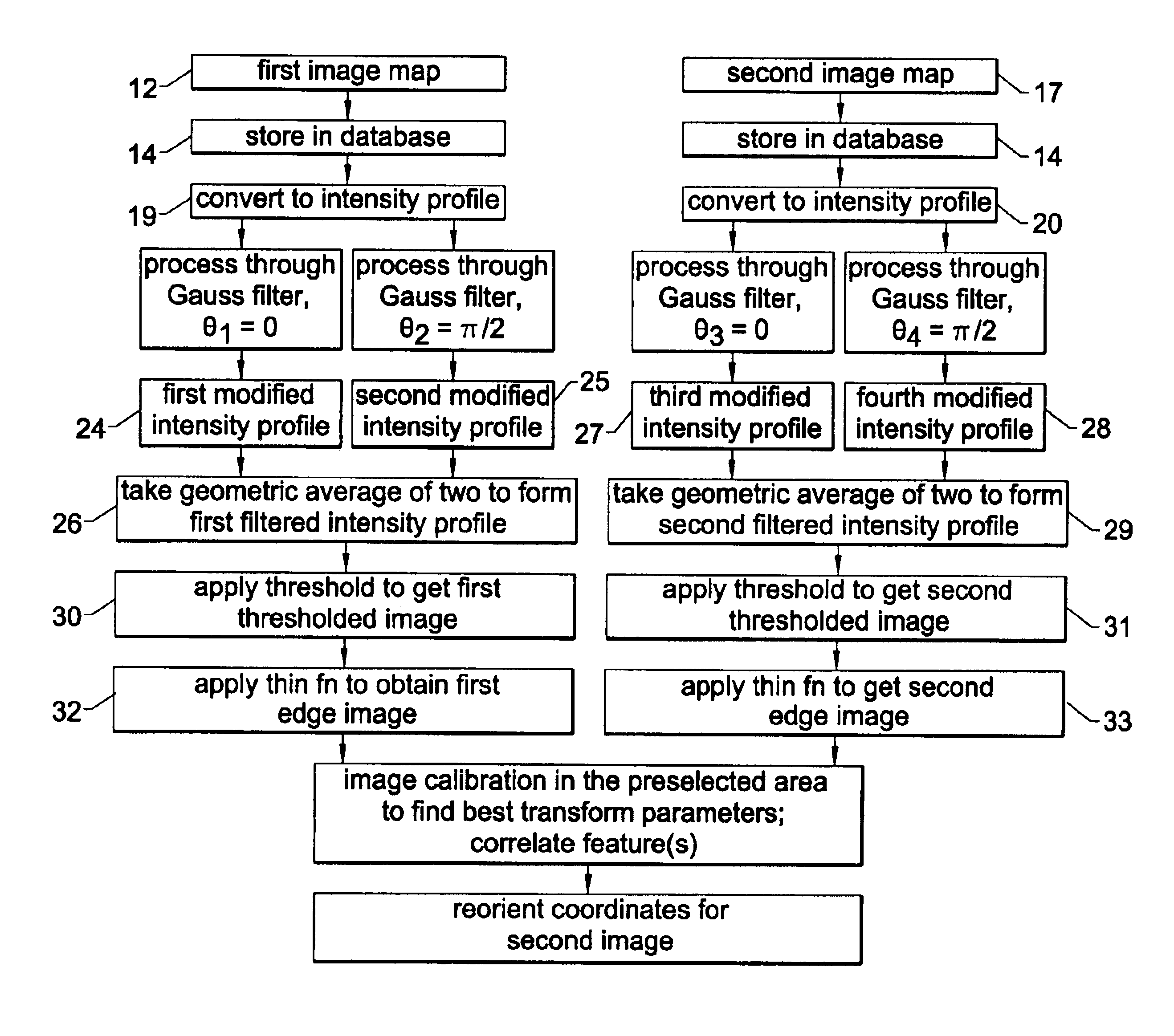
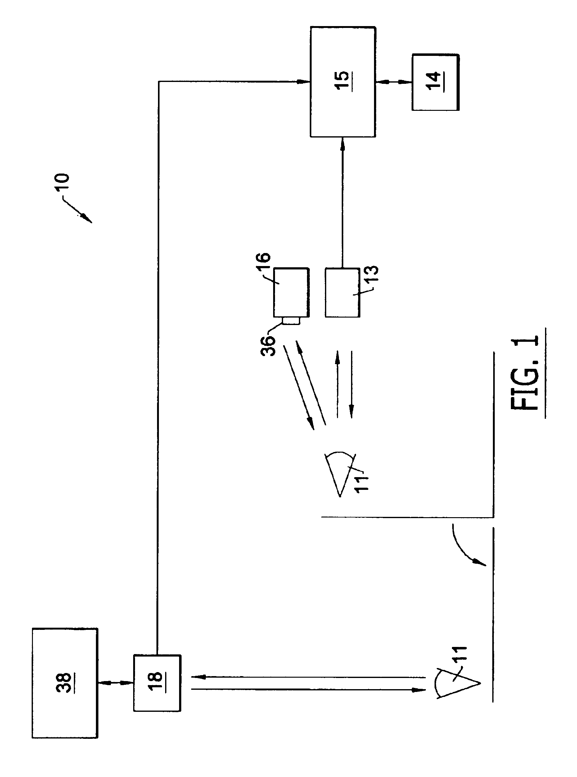
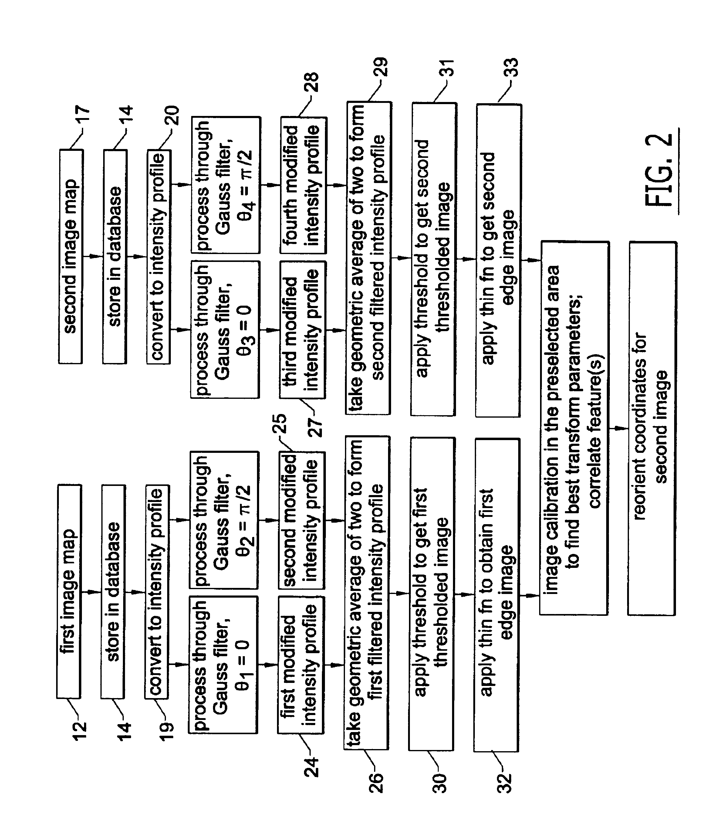
A schematic diagram of a system 10 of the invention is shown in FIG. 1, data flow and resulting images in FIG. 2, and original and processed images in FIGS. 3-8. A section on the image processing algorithms embodied herein follows the description of the system and method. In an exemplary embodiment of the system 10, a patient's eye 11 is image mapped in a substantially upright position by capturing a first video image 12 using a camera such as a charge-coupled-device (CCD) camera 13. Such an image 12 is illustrated in FIG. 3. The first image 12 is stored in a database 14 in electronic communication with a computer 15 and labeled as an original image from a first measurement.

Next an objective measurement is made on the eye 11 to determine a desired correction profile, using a measurement system 16 such as that disclosed in copending application Ser. No. 09 / 566,668, although this is not intended as a limitation.

Once the correction profile is determined, the patient is made ready for s...

second embodiment

the present invention includes an orientation system 40 for eye surgery for correcting at least astigmatism, which is shown schematically in FIG. 9. The graphical user interface and elements thereof are illustrated in FIG. 10. A means for making two alignment marks 41,42 on an eye 43 of a patient (FIG. 10) with the patient in a first position may comprise, for example, an ink pen 44, although this is not intended as a limitation, and alternative marking means known in the art may also be used. In current use, the first position typically comprises a seated upright position. In a preferred embodiment, the alignment marks 41,42 are made at the “3 o'clock” and “9 o'clock” positions to the eye's sclera 45 just outside the margin of the limbus 46. In other words, the alignment marks 41,42 are made at approximately the Π / 2 and 3Π / 2 radial positions relative to the limbus 46, with a 0 radial position comprising a top point of the limbus 46. Thus the alignment marks 41,42 are made substanti...


PUM


Abstract

An orientation system for corrective eye surgery includes a camera for performing a first image mapping of a patient's eye using a predetermined eye feature and software for processing the first image map to determine an edge location of the feature. A second image mapping of the eye is performed with the patient in a different position. The second image map is processed to locate the predetermined eye feature. Correlation of the mappings is used to calculate an orientational change of the eye between the two positions. The data are used to calculate an adjustment to be applied to a corrective prescription for application by the surgical procedure.

Description

BACKGROUND OF THE INVENTION1. Field of the InventionThe present invention relates to systems and methods for improving objective measurements preceding corrective eye surgery, and, more particularly, to such systems and methods for improving results of corrective laser surgery on the eye.2. Description of Related ArtLaser-in-situ-keratomileusis (LASIK) is a common type of laser vision correction method. It has proven to be an extremely effective outpatient procedure for a wide range of vision correction prescriptions. The use of an excimer laser allows for a high degree of precision and predictability in shaping the cornea of the eye. Prior to the LASIK procedure, measurements of the eye are made to determine the amount of corneal material to be removed from various locations on the corneal surface so that the excimer laser can be calibrated and guided for providing the corrective prescription previously determined by the measurements. Refractive laser surgery for the correction of ...

Claims


Application Information

Patent Timeline
IPC IPC(8): A61B3/15A61F9/008A61F9/01A61F9/007A61B3/10G06T1/00G06T7/60
CPCA61F9/00804A61F2009/0088A61F2009/00872A61F2009/00846
Inventor GRAY, GARY PAULCAMPIN, JOHN ALFREDSHEN, QIPING
Owner ALCON INC
Learn More