Laser cutting of stents and other medical devices

a technology of stents and cutting blades, applied in the direction of manufacturing tools, blood vessels, other domestic objects, etc., can solve the problem of not being able to cut as effectively

Inactive Publication Date: 2005-03-15
SCI MED LIFE SYST
View PDF42 Cites 107 Cited by
  • Summary
  • Abstract
  • Description
  • Claims
  • Application Information

AI Technical Summary

Benefits of technology

The invention is also directed to a method of processing a stent preform comprising the steps of providing a stent preform, providing a laser system which produces a radiation pulse for each pump period. The laser system comprises a) a resonator cavity for resonating laser radiation b) a gain medium contained in the resonator cavity and c) a pump for periodically pumping the gain medium. The method further comprises the steps of conditioning the radiation pulse by suppressing a portion of, but not the entirety of the radiation pulse to produce conditioned radiation, outputting the conditioned radiation in the form of a laser beam, directing the laser beam at the stent preform and impinging the laser beam onto the stent preform to cut a desired pattern in the stent preform.
The invention is also directed to a method of processing a medical device preform comprising the steps of providing a medical device preform, providing a laser system comprising a resonator cavity for resonating laser radiation, a gain medium contained in the resonator cavity and a pump for periodically pumping the gain medium where the laser system producing a radiation pulse for each pump period, conditioning the radiation pulse by suppressing a portion of, but not the entirety of the radiation pulse to produce conditioned radiation, outputting the conditioned radiation in the form of a laser beam, directing the laser beam at the medical device preform, and impinging the laser beam onto the medical device preform to modify the surface of the medical device preform.

Problems solved by technology

The initial part of the pulse, labeled as A and the tail end of the pulse, labeled as C, produce heating and melting of materials such as metals causing recrystallization of the metal and microcracks and is not as effective in cutting as the more intense portion of the beam.

Method used


Image

  • Laser cutting of stents and other medical devices
  • Laser cutting of stents and other medical devices
  • Laser cutting of stents and other medical devices

Examples


Embodiment Construction

While this invention may be embodied in many different forms, there are shown in the drawings and described in detail herein specific embodiments of the invention. The present disclosure is an exemplification of the principles of the invention and is not intended to limit the invention to the particular embodiments illustrated.

For the purposes of this disclosure, like reference numerals in the figures shall refer to like features unless otherwise indicated.

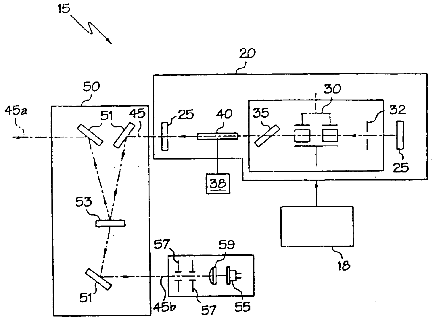
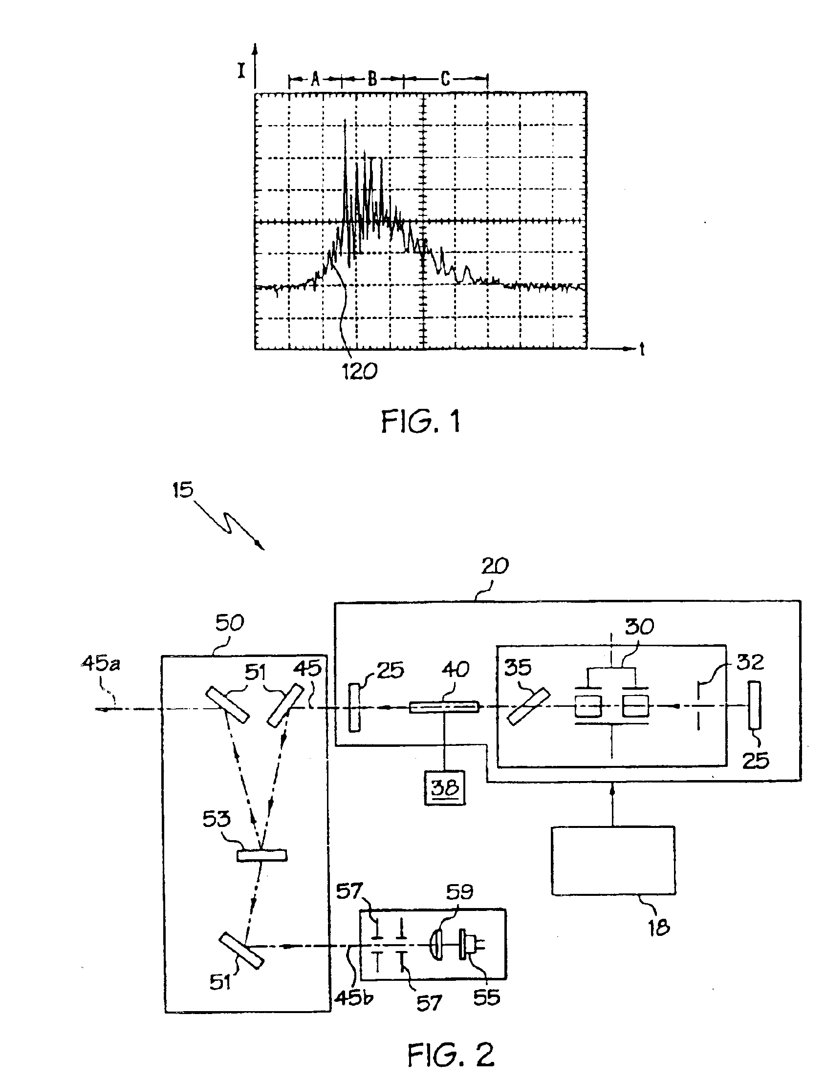
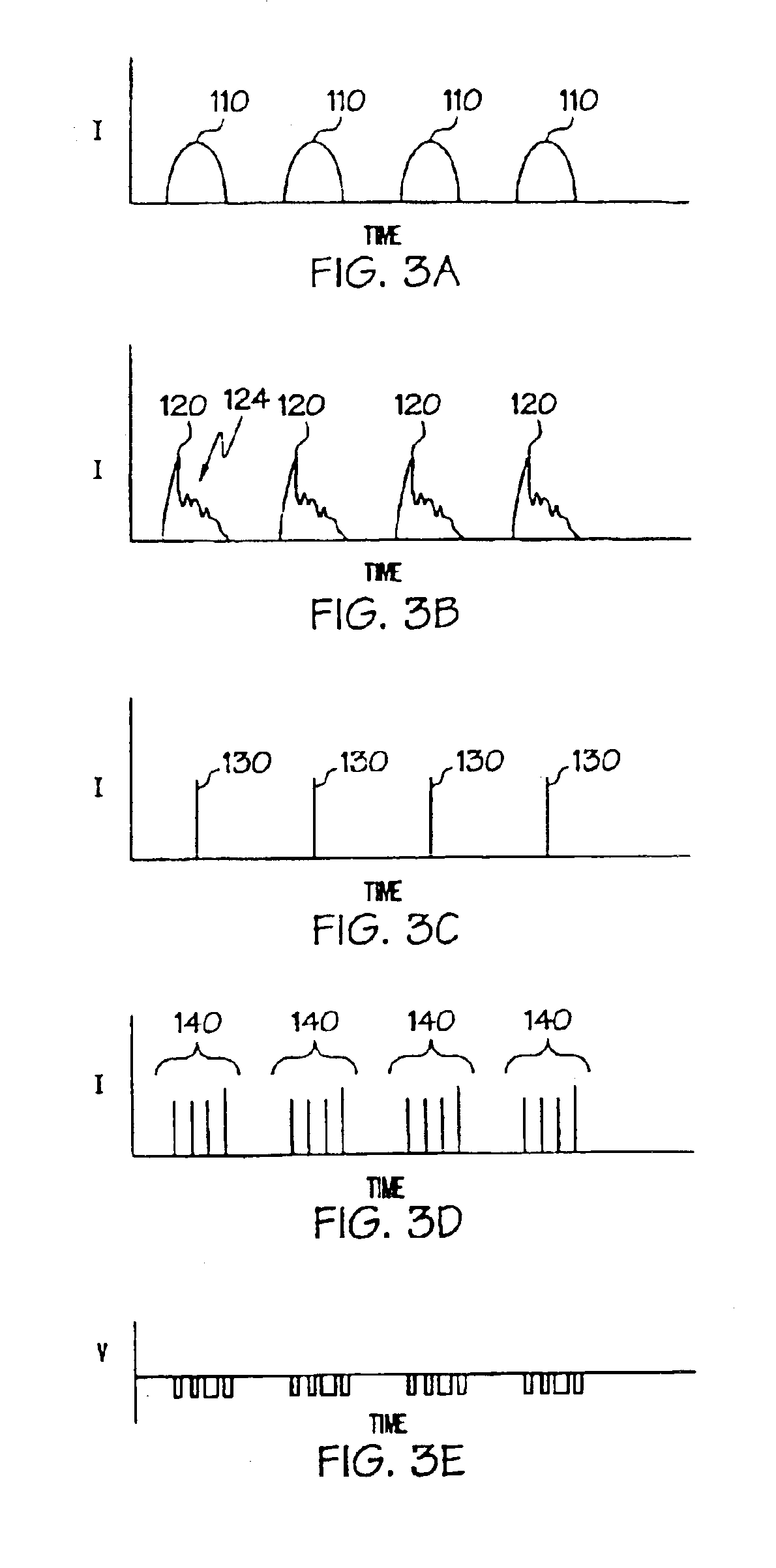
The present invention, in some of its embodiments, provides methods for manipulating laser beams for cutting stent preforms, stents and other workpieces. The invention also provides for laser systems for generating the laser beams used in the practice of the inventive methods.

In one embodiment, the present invention is directed to a method of processing a stent preform using a laser beam. The stent preform may be in the form of a tube, a sheet or any other shape of material into which a stent design is cut. Desirably, the stent pr...


PUM

PropertyMeasurementUnit
wavelength rangeaaaaaaaaaa
polymericaaaaaaaaaa

Abstract

A desired pattern may be cut into a stent preform by impinging a laser beam onto the stent preform. The laser beam is formed using a laser system comprising a resonator cavity for resonating laser radiation, a gain medium contained in the resonator cavity, a pump for periodically pumping the gain medium and an electro-optical modulator in communication with the resonator cavity. The laser system produces a radiation pulse for each pump period. Each radiation pulse is conditioned by suppressing at least a portion of the pulse. The pulse may also be modulated with an electro-optical modulator to produce a pulse train of ordered pulses of radiation. Each pulse train is output from the optical cavity as an output laser beam which is directed at the stent preform to cut a desired pattern in the stent preform.

Description

BACKGROUND OF THE INVENTIONA stent is a radially expandable endoprosthesis which is adapted to be implanted in a body lumen. Stents are typically used in the treatment of atherosclerotic stenosis in blood vessels and the like to reinforce body vessels and to prevent restenosis following angioplasty in the vascular system. They have also been implanted in urinary tracts and bile ducts and other bodily lumen. They may be self-expanding or expanded by an internal radial force, such as when mounted on a balloon.Delivery and implantation of a stent is accomplished by disposing the stent about a distal portion of the catheter, percutaneously inserting the distal portion of the catheter in a bodily vessel, advancing the catheter in the bodily lumen to a desired location, expanding the stent and removing the catheter from the lumen. In the case of a balloon expandable stent, the stent is mounted about a balloon disposed on the catheter and expanded by inflating the balloon. The balloon may ...

Claims


Application Information

Patent Timeline
Patent Type & Authority Patents(United States)
IPC IPC(8): B23K26/06A61F2/06A61F2/90B23K26/38B23K26/40
CPCB23K26/063B23K26/0639B23K26/0643B23K26/4005B23K26/4065B23K26/0648A61F2/91B23K2203/14B23K2201/06B23K2203/04B23K26/064B23K26/0622B23K26/40B23K2101/06B23K2103/05B23K2103/14B23K2103/42B23K2103/50
Inventor SHAPOVALOV, VITALYROUSSOV, VLADIMIR A.VEIKO, VADIM P.
Owner SCI MED LIFE SYST
Why Eureka
Try Eureka