Light weight hydrogen tank

a hydrogen tank and light weight technology, applied in the direction of fuel systems for specific fuels, container discharging methods, transportation and packaging, etc., can solve the problems of heavy tanks, difficult to realize endurance advantages, heavy tanks, etc., and achieve the effect of preventing icing

Inactive Publication Date: 2005-03-22
HUGHES ELECTRONICS
View PDF14 Cites 7 Cited by
  • Summary
  • Abstract
  • Description
  • Claims
  • Application Information

AI Technical Summary

Benefits of technology

The above-stated need is satisfied by the present invention which includes a thin-walled spherical metal shell surrounded by a concentric metal and composite shell separated by a radial insulating gap. The inner shell carries the hydrogen mass and the gap between the shells is evacuated to a high vacuum. The outer shell preferably has a sandwich structure whose skins can be joined with a low conductive material. The mutually facing surfaces of the inner and outer shells are coated with a low emissivity metal, such as copper. The two shells are joined at two opposing equatorial locations. The vacuum gap and low emittance surface finishes on the two shells provide appropriate thermal insulation. External stiffening ribs could also be employed for shell stabilization where desired. An electrical heater conducts a controlled amount of heat to the outer shell. Radiation couples the heat to the inner shell and thus to the fuel in order to control the evaporation rate of the hydrogen. A second electrical heater is placed on the outer skin of the outer shell to prevent icing during ascent and descent.

Problems solved by technology

However, the use of hydrogen has disadvantages which make it difficult to realize the endurance advantage.
Due to these properties of hydrogen, conventional designs result in heavy tanks with the weight offsetting most of the endurance improvements that the energy density of hydrogen might provide.
For a required storage time of several weeks, such a design results in a very heavy tank on the order of 100% of the weight of the fuel.

Method used


Image

  • Light weight hydrogen tank
  • Light weight hydrogen tank
  • Light weight hydrogen tank

Examples


Embodiment Construction

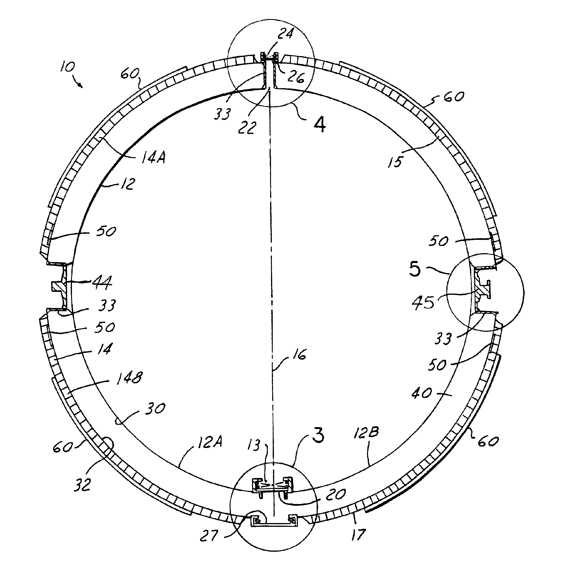
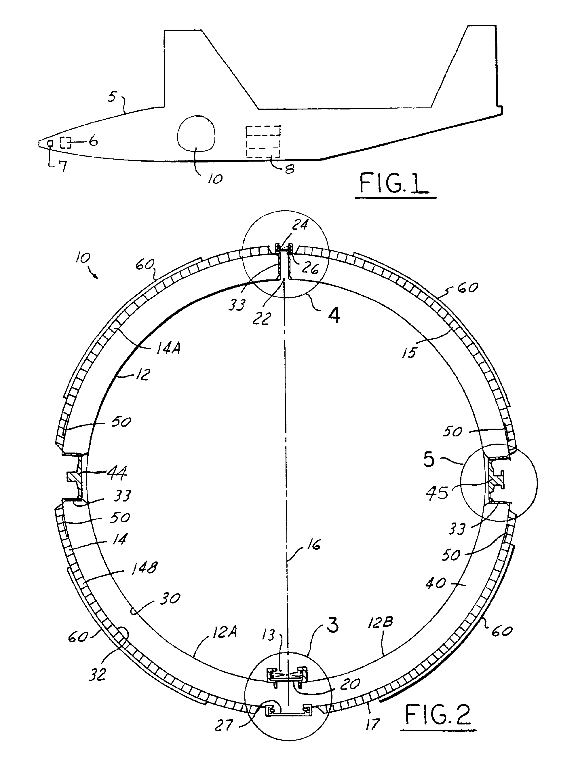
The present invention has particular use with stratospheric vehicles, such as hydrogen powered airplanes. A representative vehicle of this type is shown in FIG. 1 and designated by the reference numeral 5. The light weight hydrogen tank in accordance with the present invention is positioned in the airplane 5 and designated by the reference numeral 10. The airplane 5 also typically will include a fuel cell 6, turbocharger 7 and communication payload 8. The details of the hydrogen tank 10 are depicted in FIG. 2.

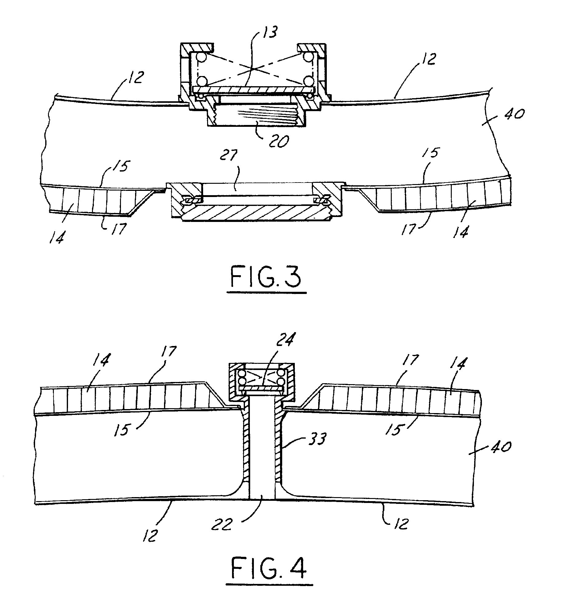
The tank 10 includes an inner spherical shell member 12 and an outer spherical shell member 14. The inner shell member is preferably made of a metal material in a spherical shape. In this regard, two semi-spherical halves 12A and 12B of the shell 12 are welded together along the seam or girth 16 in order to form the shell member 12. A port member or opening 20 is provided at one pole of the shell member 12 and contains a valve mechanism 13 for filling and draining of the hydrog...


PUM


Abstract

A light weight fuel tank for a hydrogen powered airplane used as a platform for communication repeaters for communication services. An outer spherical shell member of a sandwich configuration surrounds an inner thin walled spherical shell member in which the liquid hydrogen is contained. A radial gap between the shell members is evacuated to a high vacuum. The facing surfaces of the shell members are coated with a low emissivity material. Electrical heaters are provided to control the evaporation rate of the hydrogen to match the fuel usage and to prevent icing during ascent and descent of the airplane.

Description

TECHNICAL FIELDThe present invention relates to hydrogen powered vehicles, such as airplane, and more particularly to improved hydrogen fuel tanks for such vehicles.BACKGROUND ARTStratospheric vehicles, such as airplanes, have been proposed in recent years as platforms for communication repeaters which provide a variety of communication services. One type of vehicle which can be used for these platforms is a hydrogen powered airplane. The high density of hydrogen can achieve the long endurance at high altitudes needed for commercial communication systems. Compared to gasoline, hydrogen, when combined with atmospheric oxygen, yields about three times the energy density of gasoline. The time aloft duration of airplanes fueled by hydrogen can be measured in weeks.However, the use of hydrogen has disadvantages which make it difficult to realize the endurance advantage. Hydrogen, even in liquid form, requires a relatively large volume storage tank. Also, the low liquid temperatures requi...

Claims


Application Information

Patent Timeline
Patent Type & Authority Patents(United States)
IPC IPC(8): B64D37/30B64D37/00
CPCB64D37/00B64D37/30Y02T90/44Y02T50/44Y02T50/40Y02T90/40
Inventor ROSEN, HAROLD A.WITTMANN, ALOISPANO, SCOTT B.
Owner HUGHES ELECTRONICS
Why Eureka
Try Eureka