Multi-color multiplexed analysis in a bio-separation system

a bioseparation system and multi-color technology, applied in the direction of optical radiation measurement, electrodialysis, spectral modifiers, etc., can solve the problems of high cost, high cost, and high cost of existing dna analysis procedures, and achieve high throughput, low cost, and high sensitive

Inactive Publication Date: 2005-03-22
QIAGEN SCIENCES LLC
View PDF55 Cites 105 Cited by
  • Summary
  • Abstract
  • Description
  • Claims
  • Application Information

AI Technical Summary

Benefits of technology

[0017]The present invention provides a simplified, low cost, efficient, highly sensitive, and high throughput multi-channel detection configuration for bio-separation (e.g., CE), which overcomes the drawback of the prior art. The present invention provides a multi-channel detection scheme based on a multi-radiation source / common detector configuration, in which detection is conducted in a time-staggered, and / or time-multiplexed detection for the channels. A single detector is coupled to a plurality of radiation sources, in a one detector / many radiation sources configuration. Each radiation source directs radiation at one detection zone of a single separation channel, and a single detector is applied to detect light emissions from the detection zones of several separation channels. There may be more than one detector in the entire detection system, each serving multiple radiation sources.
[0018]Bio-separation may be conducted simultaneously in all the channels in parallel, with detection time-staggered and / or time-multiplexed with respect to the light sources. The light sources direct radiation at the detection zones in a predetermined sequence in a cyclic manner, with the detector output synchronized to the light sources by a controller. The radiation sources and the detector are pulsed in synchronization in a time-multiplexed manner. The controller controls the detector and radiation sources in a manner to effect detection of radiation emissions from the multiple separation channels in predetermined detection cycles, wherein each detection cycle is repeated at a frequency to provide a desired detection time or duration. The controller controls the radiation sources and detector in a manner to effect detection in a repeated scanning manner, across the detection zones of the separation channels, in a time-staggered type detection. In accordance with the present invention, cross talk between channels is virtually eliminated. No moving parts are required for directing the light source or detection.
[0019]In one embodiment, low cost light emitting diodes (LEDs) (e.g., super bright LEDs) or laser diodes, instead of expensive high power lasers may be used as light sources. Alternatively, low energy lasers may be used. The incident light from the light sources may be separately directed to the detection multi-channel detection zones using optic fibers. The emitted light from the multi-channel detection zones may be directed to one or more common detectors using optic fibers. Since no moving parts are necessary, component count can be reduced. By eliminating or reducing cross talk between channels, the optical detection system design can be much simplified. Accordingly, the cost, reliability, and ease of use of the instrument is improved.

Problems solved by technology

Yet due to the complexity of the equipment that detects and measures DNA samples and the difficulty in preparing the samples, the existing DNA analysis procedures are often time-consuming and expensive.
CE techniques are employed in seemingly limitless applications in both industry and academia.
Some of the challenges in designing CE-based instruments and CE analysis protocols relates to sample detection techniques.
The main drawback of the sheath flow detector is the highly sophisticated flow system needed to ensure a reliable sheath flow.
The use of moving parts is not ideal when considering simplicity, robustness and lower cost of the instrument.
Also, the shallow focal depth of the microscope objective puts severe demands on the mechanical and optical component tolerances.
Further, the optical scanning principle reduces the duty cycle per capillary, which may impair the sensitivity when scaling up the instrument further for very high-throughput purposes.
One of the most expensive hardware components for many commercially available CE instruments with LIF detector is typically a fluorescence excitation light source, which can be a gas discharge lamp (mercury or xenon) or a laser (gas, solid state with second harmonic generation, dye, or semiconductor), that are bulky, expensive, inefficient and difficult to couple one's light output into optical fibers, thus preventing miniaturization of the optical detection system.
These light sources hinder development of small size, high-throughput and cost-effective analytical instruments, with the convenience required for rapid detection.
However, most commercially available CE instrumentation has only one capillary, and only one sample may be analyzed at a time.
However, the design of a multi-capillary DNA Analyzer utilizing LIF based detection optical systems (i.e. 8-capillary CEQTM 2000XL Instrument of Beckman Coulter) are considerably more costly and complicated than the classical slab gel-based systems.
However, because only one light source is used for the illumination, there is cross talk between the different separation channels defined by the capillaries.
Due to the existence of scatter light, cross talk cannot be prevented and the contrast ratio of detected signals will be poor due to noise in the fluorescence emission.
Furthermore, prior art single illumination source for multiple channels makes multi-wavelength LIF detection more complicated.

Method used


Image

  • Multi-color multiplexed analysis in a bio-separation system
  • Multi-color multiplexed analysis in a bio-separation system
  • Multi-color multiplexed analysis in a bio-separation system

Examples


Embodiment Construction

e present invention.

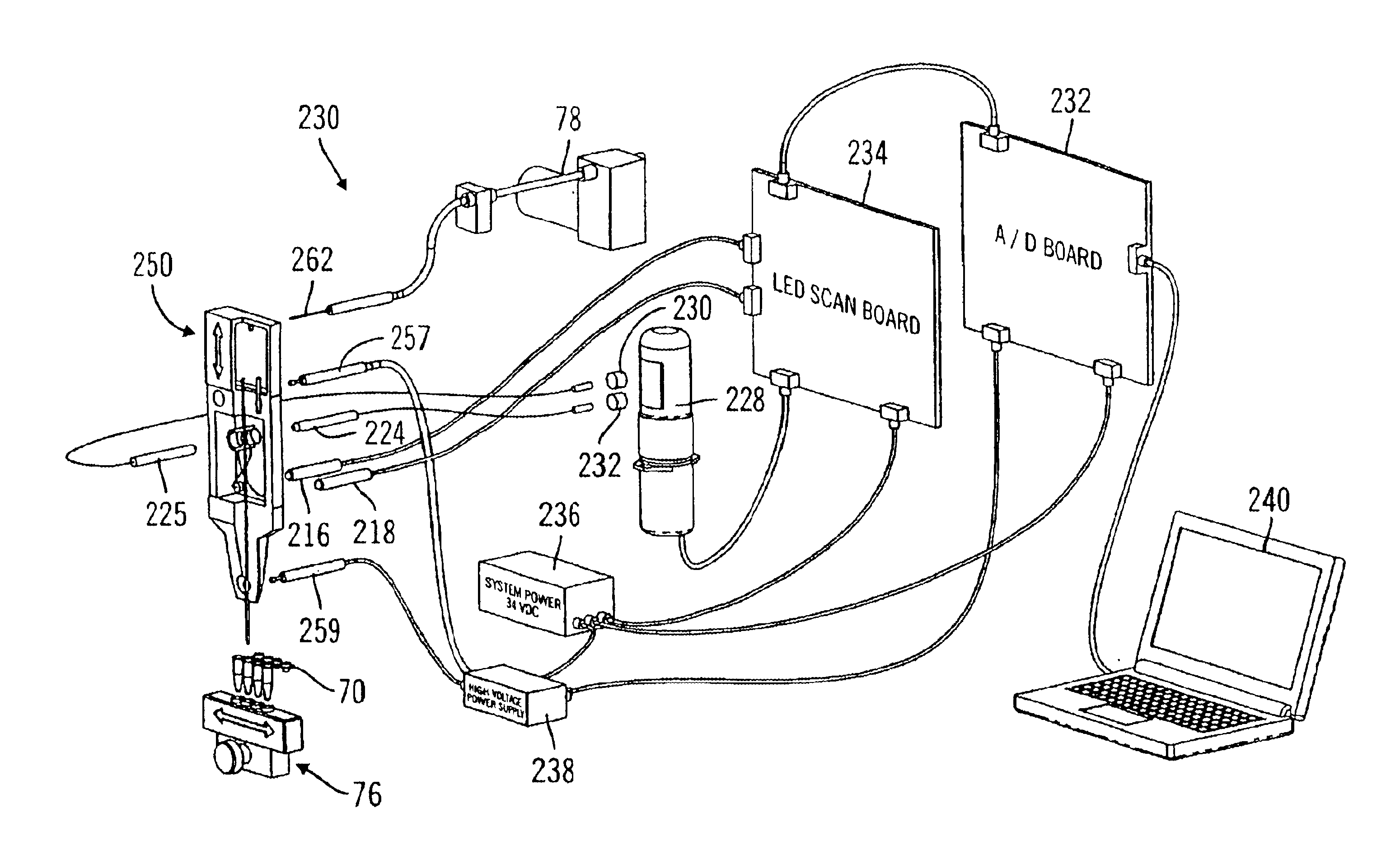
[0027]FIG. 4 is a block diagram of the control system for the incident radiation and emission detection system.

[0028]FIG. 5 is a timing diagram illustrating the pulsing for time-multiplexing of radiation sources in accordance with one embodiment of the present invention.

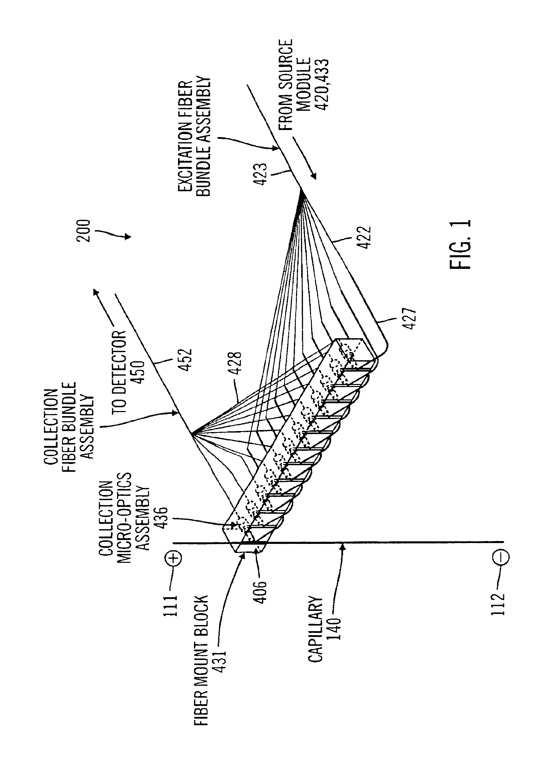
[0029]FIG. 6 is a schematic view of optical detection configuration applying a two-color excitation scheme in accordance with one embodiment of the present invention.

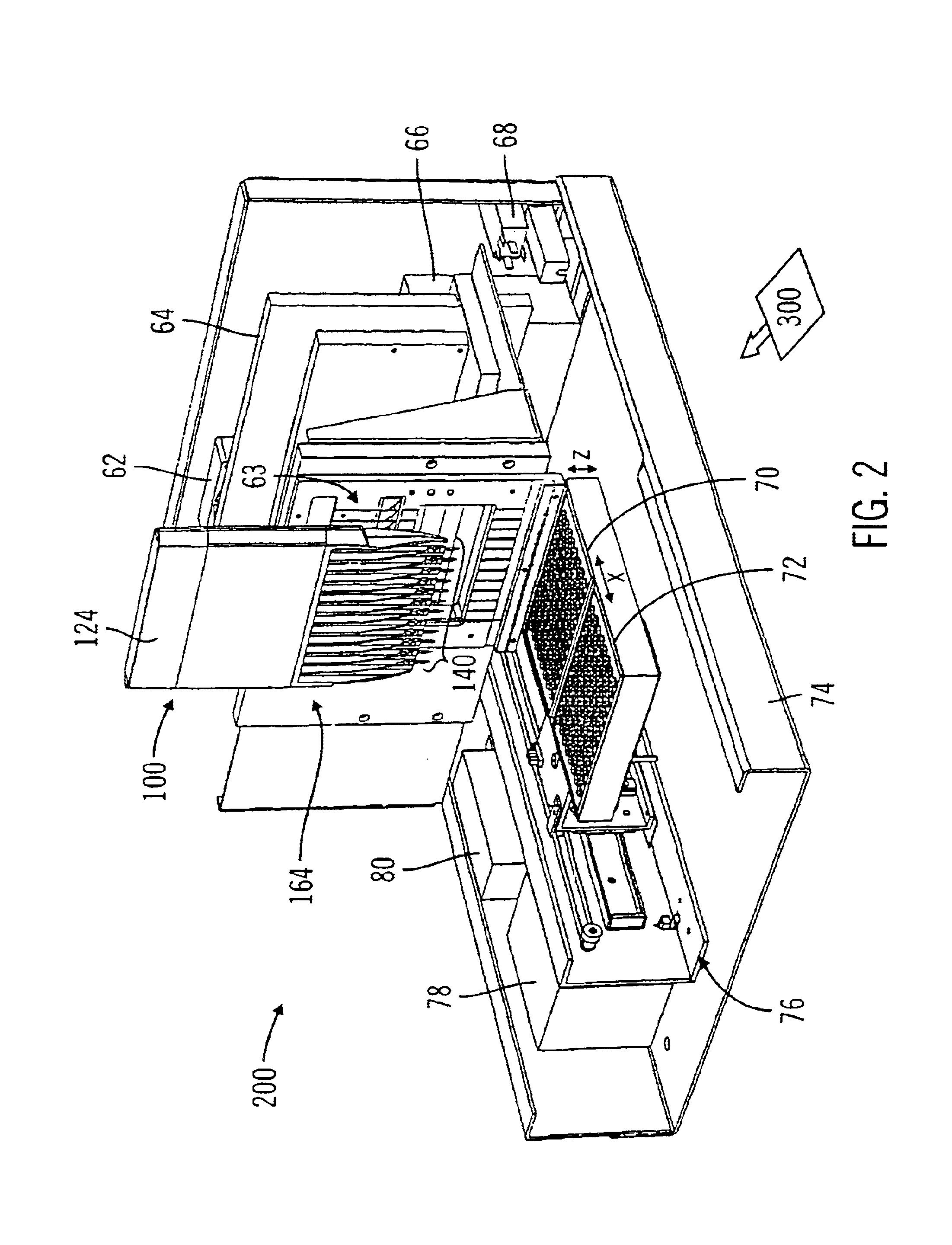
[0030]FIG. 7 is a simplified view of a bio-separation system, which incorporates the two-color incident radiation optical detection configuration of the present invention in relation to a single channel capillary cartridge, in accordance with one embodiment of the present invention.

[0031]FIG. 8 is an enlarged view of the capillary cartridge and the optical detection elements.

[0032]FIG. 9 is a schematic view of optical detection configuration applying a four-color incident radiation scheme in accordance with one embodiment of the prese...


PUM

PropertyMeasurementUnit
internal diameteraaaaaaaaaa
wavelengthaaaaaaaaaa

Abstract

A multi-channel and multi-color bio-separation detection method and apparatus in which a single detector is coupled to a plurality of radiation sources, in a one detector / many radiation sources configuration. Each radiation source directs radiation at a detection zone of a single separation channel, and a single detector is applied to detect light emissions from the detection zones associated with several radiation sources. The radiation sources are activated to direct radiation at the detection zone in a predetermined sequence and further in a cyclic manner, with the detector output synchronized to the radiation sources by a controller. Bio-separation may be conducted simultaneously in all the channels in parallel, with detection time-staggered and / or time multiplexed with respect to the light sources. In one embodiment, low cost light emitting diodes may be used as radiation sources. In another aspect, the detection scheme is configured for radiation induced fluorescence detection in an capillary electrophoresis instrument.

Description

CROSS-REFERENCE[0002]This application is a continuation-in-part and claims the priority of the following: (a) U.S. Provisional Patent Application No. 60 / 348,034, filed Oct. 19, 2001; (b) U.S. patent application Ser. No. 10 / 060,052, filed Jan. 28, 2002; and (c) U.S. patent application Ser. No. 10 / 059,993, filed Jan. 28, 2002. These applications are fully incorporated by reference as if fully set forth herein.BACKGROUND OF THE INVENTION[0003]1. Field of the Invention[0004]The present invention relates to detection techniques in bio-analysis, particularly optical detection in a multi-channel bio-separation system, and more particularly detection of emissions from radiation excitations in multi-channel capillary based electrophoresis. The present invention further relates to bio-separation instrument incorporating the detection scheme of the present invention.[0005]2. Description of Related Art[0006]Bioanalysis, such as DNA analysis, is rapidly making the transition from a purely scient...

Claims


Application Information

Patent Timeline
Patent Type & Authority Patents(United States)
IPC IPC(8): G01N27/447
CPCG01N27/44782G01N27/44721
Inventor AMIRKHANIAN, VAROUJLIU, MING-SUN
Owner QIAGEN SCIENCES LLC
Why Eureka
Try Eureka