Optical scanning lens, optical scanning device and image forming apparatus

a scanning lens and optical scanning technology, applied in the field of optical scanning lens, optical scanning device and image forming apparatus, can solve the problems of acrylic resin problem, high surface accuracy, and high cost, and achieve the effect of superior moisture absorption and double refraction properties

Inactive Publication Date: 2005-03-22
RICOH KK
View PDF65 Cites 19 Cited by
  • Summary
  • Abstract
  • Description
  • Claims
  • Application Information

AI Technical Summary

Benefits of technology

It is possible that, in any optical scanning device, a light deflector which deflects a light flux from the light source is provided and the light deflector ‘has a deflection reflecting surface and deflects the light flux at a uniform angular velocity’, and the optical scanning lens ‘has a function of causing the scanning of the surface to be scanned to be performed at a uniform velocity’.
It is possible that, in the optical scanning device, an image is formed from the light flux from the light source in the vicinity of the deflection reflecting surface of the light deflector, the image being like approximately a line long in main scanning directions. For example, it is possible that a light flux from the light source is transformed into a light-flux form (any form of a parallel light flux, a convergent light flux and a divergent light flux is possible) suitable for a subsequent optical system by a coupling lens, and, from the thus-coupled light flux, a line image long in main scanning directions is formed in the vicinity of the deflection reflecting surface of the light deflector by a line-image forming optical system such as a cylinder lens. Thereby, it is possible to correct a surface inclination of the light deflector.
According to the present invention, it is possible to achieve novel optical scanning lens, optical scanning device and image forming apparatus.
An optical scanning lens according to the present invention is made of polyolefin resin which is superior in a moisture-absorption property and a double-refraction property, and has an internal refractive-index distribution controlled effectively, thereby being not likely to be affected by changes in environmental conditions such as temperature, humidity and so forth.
Further, an optical scanning device according to the present invention uses the above-mentioned optical scanning lens, and, thereby, it is possible to achieve an optical scanning device which is not likely to be affected by environmental fluctuation and is always satisfactory.
Furthermore, an image forming apparatus according to the present invention uses the above-mentioned optical scanning device, and, thereby, it is possible to achieve an image forming apparatus which is not likely to be affected by environmental fluctuation and is always satisfactory.

Problems solved by technology

One problem occurring when an optical scanning lens is formed by molding plastic material is that a refractive-index distribution develops inside the thus-formed optical scanning lens.
Acrylic resin is problematic because a moisture absorption is large although double refraction (photoelasticity constant) is small, and, in particular, a surface accuracy is likely to deteriorate as environment changes.
Although PC (polycarbonate) has a high refractive index and a small moisture absorption, a photoelasticity constant thereof is very large and thereby double refraction is likely to develop, and wavefront aberration of a light flux transmitted thereby is likely to deteriorate.
However, polyolefin resin has a relatively large mold shrinkage coefficient in comparison to other plastic materials, molding is somewhat difficult, and a refractive-index distribution is likely to develop unless molding conditions such as molding pressure, molding temperature and so forth are made to be the optimum ones.

Method used


Image

  • Optical scanning lens, optical scanning device and image forming apparatus
  • Optical scanning lens, optical scanning device and image forming apparatus
  • Optical scanning lens, optical scanning device and image forming apparatus

Examples


Embodiment Construction

First, a refractive-index distribution will now be described supplementarily.

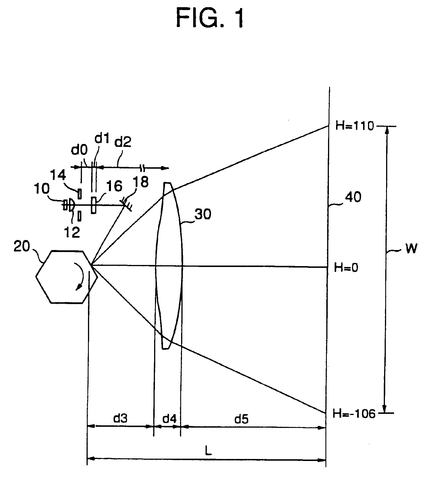
A refractive-index distribution Δn(x) is defined as one obtained as a result of values of ‘a two dimensional absolute refractive index’ in a ‘x-y section’ parallel to an optical axis and to sub-scanning directions of an optical scanning lens (30) shown in FIG. 2C being averaged in y-axis directions, and being expressed as a one dimensional relative refractive index with respect to x-axis directions (see FIG. 2E).

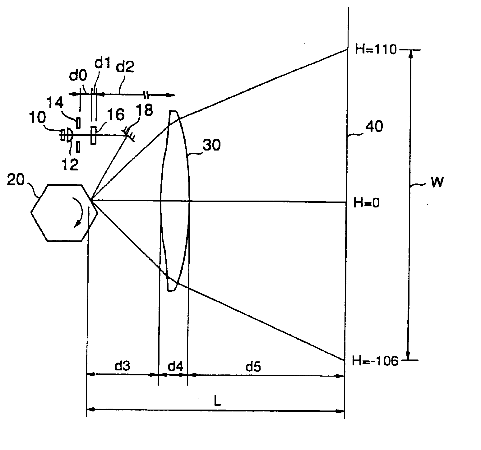
‘A range, which a light flux passes through, of a lens’, is, ‘a range, which a light flux deflected by a light deflector passes through when being deflected, of an optical scanning lens’. In details, with respect to main scanning directions, ‘a range, which a light flux passes through and which corresponds to an effective writing width of a surface to be scanned, of a lens’, is a range, which a deflected light flux passes through, in the lens, with respect to sub-scanning directions, it is preferabl...


PUM

PropertyMeasurementUnit
photoelasticityaaaaaaaaaa
angular velocityaaaaaaaaaa
velocityaaaaaaaaaa

Abstract

An optical scanning lens which is used in a scanning and age forming optical system which gathers a light flux deflected by a light deflector in the vicinity of a surface to be scanned. The lens is formed by plastic molding of polyolefin resin, and the following condition is satisfied: 0<|Δn(x)−min[Δn(x)]|<34×10−5, where Δn(x) denotes a refractive-index distribution existing inside the lens, in a range which the light flux passes through, in the lens, and min[Δn(x)] denotes the minimum value of the Δn(x).

Description

BACKGROUND OF THE INVENTION1. Field of the InventionThe present invention generally relates to an optical scanning lens, an optical scanning device and an image forming apparatus.2. Description of the Related ArtAn optical scanning device, which deflects a light flux from a light source at a uniform angular velocity by a light deflector having a deflection reflecting surface, converges the deflected light flux on a surface to be scanned as a beam spot by a scanning and image forming optical system, and, thus, scans the surface to be scanned at a uniform velocity with the beam spot, is well-known in relation to ‘image forming apparatus’ such as a digital copier, an optical printer, a laser plotter, a digital plate maker and so forth.FIG. 1 illustrates one example of an optical scanning device.A divergent light flux emitted by a semiconductor laser 10 is transformed into a light flux form (such as a parallel light flux or the like) suitable for subsequent optical systems by a coupling...

Claims


Application Information

Patent Timeline
Patent Type & Authority Patents(United States)
IPC IPC(8): B41J2/435B41J2/47G02B26/12G02B13/00G02B3/00G02B26/10C08L23/00G02B1/04
CPCB41J2/471G02B3/0087G02B26/125G02B13/0005Y10S359/90
Inventor SUHARA, HIROYUKIITOH, SATORUITO, TATSUYAUEDA, TAKESHIHAYASHI, YOSHINORIAOKI, MAGANETAKANASHI, KENICHIYAMAGUCHI, TAKAOKOUCHIWA, TAIRAHIRAKURA, KOJISUZUKI, SEIZO
Owner RICOH KK
Why Eureka
Try Eureka