Semi-transparent time division multiplexer/demultiplexer

a time division multiplexer and semi-transparent technology, applied in time-division multiplexing selection, multiplex communication, synchronisation signal speed/phase control, etc., can solve the problems of prohibitive expansion cost, limited capacity of existing waveguide media, etc., and achieve the effect of transparency of toh

Inactive Publication Date: 2005-03-22
CIENA
View PDF11 Cites 25 Cited by
  • Summary
  • Abstract
  • Description
  • Claims
  • Application Information

AI Technical Summary

Benefits of technology

The present invention is therefore organized about the concept of providing a semi-transparent time division multiplexer / demultiplexer that transmits low rate tributaries from one location to another using a high rate aggregate connection, while preserving substantially all of the TOH and payload for each tributary signal. Transparency of the tributary TOH is accomplished by interleaving both the TOH and the Payload of each tributary into the high rate aggregate signal. Some TOH bytes may be tunneled or re-mapped into unused / undefined TOH locations in the aggregate signal to allow transparency of the TOH without corrupting the aggregate.

Problems solved by technology

While this is a useful technique for carrying plural information sources on a single channel, its capacity is limited by fiber dispersion and the need to generate high peak power pulses.
While the need for communication services increases, the current capacity of existing waveguiding media is limited.
Although capacity may be expanded e.g., by laying more fiber optic cables, the cost of such expansion is prohibitive.
Even in DWDM systems, however, fiber capacity is being exceed, resulting in congestion of the data carried on many networks.
This is, however, quite expensive and time consuming.
To date, the prior art has failed to provide an effective, reliable, and cost-efficient multiplexer / demultiplexer for serving this purpose.
A main difficulty in this regard relates to maintenance of the Payload and transport overhead (TOH) bytes in the tributary signals.
Once the lower data rate tributary signals are combined into the aggregate according to a standard SONET / SDH method, the overhead bytes in the tributary signals are irretrievably lost.
This seriously limits the ability to provide line maintenance signaling, section / line / path performance monitoring, and fault isolation for the tributary signals.

Method used


Image

  • Semi-transparent time division multiplexer/demultiplexer
  • Semi-transparent time division multiplexer/demultiplexer
  • Semi-transparent time division multiplexer/demultiplexer

Examples


Embodiment Construction

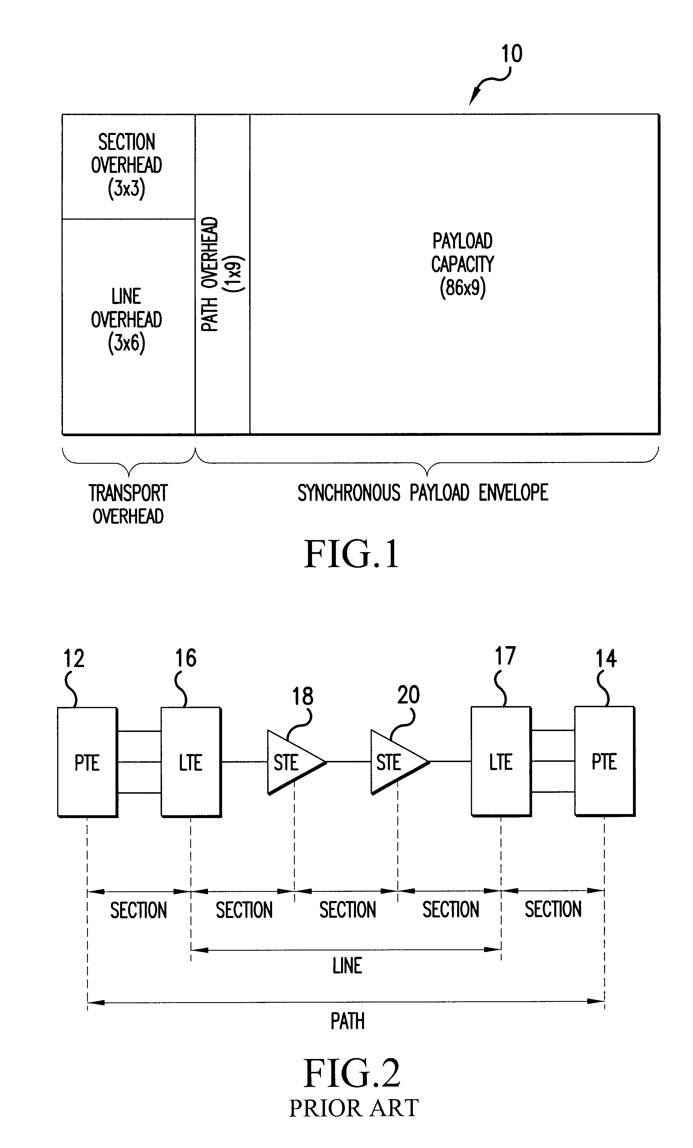
As is known, the SONET standards ANSI T1.105 and Bellcore GR-253-CORE, define a physical interface, optical line rates known as optical carrier (OC) signals, a frame format, and an operation, administration, maintenance, and provisioning (OAM&P) protocol. User signals are converted into a standard electrical format called the synchronous transport signal (STS), which is the equivalent of the optical signal to be transmitted on an optical network. The basic STS-1 frame consists of 90 columns by 9 rows of bytes and has a length of 125 microseconds, resulting in a rate of 51.840 Mb / s. Higher rates (STS-N, STS-Nc) are built from STS-1, and lower rates are subsets of STS-1. Advantageously, the SONET standard facilitates multiplexing of various STS-N input streams onto optical fiber channels.

Turning to FIG. 1, there is illustrated the structure of a basic STS-1 frame 10. As shown, the frame comprises a transport overhead (TOH) consisting of three columns and 9 rows, and a synchronous payl...


PUM


Abstract

A semi-transparent time division multiplexer/demultiplexer that transmits low rate tributaries from one location to another using a high rate aggregate connection, while preserving substantially all of the TOH and payload for each tributary signal. Transparency of the tributary TOH is accomplished by interleaving both the TOH and the Payload of each tributary into the high rate aggregate signal. Some TOH bytes may be tunneled or re-mapped into unused/undefined TOH locations in the aggregate signal to allow transparency of the TOH without corrupting the aggregate. Errors may be handled by tunneling BIP bytes into unused/undefined aggregate locations and updating the tunneled bytes with error masks calculated at each network elements. Alternatively errors may be forwarded by using an error mask generated from the tributary BIP locations and inserting the mask into the associated aggregate BIP locations. The mask in the aggregate BIP is updated with error masks calculated at each network elements. Re-timing of TOH to a synchronized clock in the tributary framer circuits can be accomplished using controlled slips of overhead frames, whereby an entire frame is dropped or added depending on the relationship of the received clock and the synchronized clock. DCC bytes may be re-timed by adding or deleting flag bytes occurring between respective DCC packets. Re-timing of the aggregate TOH to a transmit clock may be accomplished in a similar manner.

Description

FIELD OF THE INVENTIONThe present invention is directed to an optical multiplexer / demultiplexer for use in a dense wavelength division multiplexed optical system.BACKGROUND OF THE INVENTIONOptical communication systems are a substantial and fast growing constituent of communication networks. The expression “optical communication system,” as used herein, relates to any system that uses optical signals to convey information across an optical waveguiding medium, for example, an optical fiber. Such optical systems include but are not limited to telecommunication systems, cable television systems, and local area networks (LANs). Currently, the many optical communication systems are configured to carry an optical channel of a single wavelength over one or more optical waveguides. To convey information from plural sources, time-division multiplexing is frequently employed (TDM). In time-division multiplexing, a particular time slot is assigned to each signal source, the complete signal bei...

Claims


Application Information

Patent Timeline
Patent Type & Authority Patents(United States)
IPC IPC(8): H04J3/16H04Q11/04H04L7/04
CPCH04J3/1611H04L2007/045H04J2203/006
Inventor MEAGHER, KEVIN S.VAUGHN, MICHAELWESTDORP, JAMES
Owner CIENA
Why Eureka
Try Eureka