Method and apparatus for particle agglomeration

a particle agglomeration and particle technology, applied in the direction of electric supply techniques, séparation processes, auxillary pretreatment, etc., can solve the problems of inefficiency of techniques, and achieve the effect of increasing the adhesion of charged particles and enhancing the mixing of charged particles

Inactive Publication Date: 2005-03-29
HANSOM ENVIRONMENTAL PROD
View PDF19 Cites 49 Cited by
  • Summary
  • Abstract
  • Description
  • Claims
  • Application Information

AI Technical Summary

Benefits of technology

[0029]The mixing of the charged particles may be enhanced by acoustic agitation downstream from the ionisers.
[0030]The p

Problems solved by technology

As mentioned above, these tech

Method used


Image

  • Method and apparatus for particle agglomeration
  • Method and apparatus for particle agglomeration
  • Method and apparatus for particle agglomeration

Examples


first embodiment

[0041]FIGS. 1-3 illustrate the particle agglomeration apparatus of this invention. In this embodiment, precharged particles of different sizes in an airstream are caused to have differential speeds so as to promote mixing of the particles in the longitudinal direction of motion. The enhanced mixing results in agglomeration of the particles.

[0042]As shown in FIG. 1, a duct 10 of substantially constant cross section is connected to a second duct 11 having a substantially constant cross section which is significantly greater than the cross section of duct 10. The duct 10 is connected to the duct 11 by an Evasé portion 12 which has a progressively increasing cross section. The ducting 10, 11, 12 provides a conduit for a gas stream.

[0043]An AC ioniser 14 is located in the duct 10 to charge the particles in the gas stream. The AC ioniser 14, which is shown schematically in block form in FIG. 1, is shown in more detail in FIG. 2. The AC ioniser 14 comprises a series of spaced electrodes 15...

second embodiment

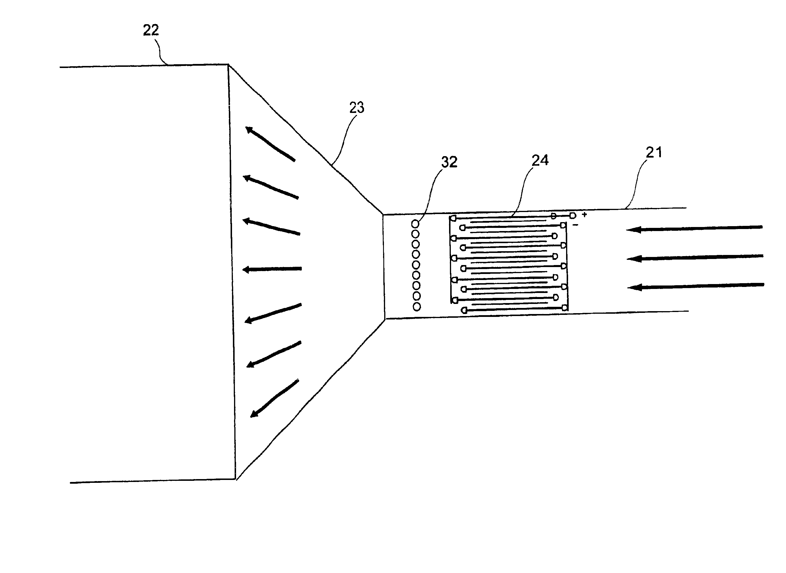
[0057]the invention is illustrated in FIGS. 5 to 9. In this embodiment, the gas stream containing the dust particles and other pollutants is divided into a series of parallel substreams which are passed through a bipolar charger so that the particles in adjacent substreams are charged to opposite polarity. The substreams are then deflected to cause adjacent substreams to merge and / or cross, thereby promoting mixing of the particles and enhancing agglomeration. That is, as the substreams merge or cross, oppositely charged particles will come into close proximity and will be attracted to each other. Consequently, they agglomerate into larger particles which can be filtered more easily from the gas stream subsequently, using known techniques.

[0058]As shown in FIG. 5, a duct 21 receives a high velocity flow of gas containing dust particles and other contaminants, in the direction shown by the arrows. The duct 21 may be connected to a larger duct 22 via an Evasé portion 23, in order to s...


PUM

PropertyMeasurementUnit
Flow rateaaaaaaaaaa
Polarityaaaaaaaaaa
Sizeaaaaaaaaaa

Abstract

Fine particles of dust and other pollutants in gas streams are agglomerated to form larger particles which are more easily filtered in downstream processing. In one embodiment, particles in successive portions of the gas stream are charged with opposite polarity, and the gas stream is introduced into an Evasé portion (12) to slow it down. Particles of different sizes have differential deceleration and therefore mix generally in the direction of flow, leading to agglomeration of oppositely-charged particles. In another embodiment, a gas stream is divided into substreams in respective parallel passages, and the particles in adjacent passages are charged to opposite polarity. Deflectors at the downstream end of the passages cause substreams of particles of opposite polarity to mix, with resultant agglomeration of oppositely charged particles.

Description

[0002]THIS INVENTION relates to method and apparatus for particle agglomeration. In particular, the invention is directed to electrostatic agglomerators for use in air pollution control.BACKGROUND ART[0003]Many industrial processes result in the emission of small hazardous particles into the atmosphere. For example, toxic airborne byproducts of coal combustion tend to concentrate in the fine particulate fraction of emissions due to the heavy metals and heavy organic material in the coal. Many of the trace metals, such as arsenic, cadmium, nickel, selenium and their compounds, volatise at the high combustion temperatures and either nucleate homogeneously or condense predominantly on the fine fly ash particles as the flue gases cool. The same is true of some of the hazardous organic air pollutants.[0004]The toxic particles which are formed by homogenous nucleation are very fine sub-micron particles. As these fine particles are able to enter the human respiratory system, they pose a si...

Claims


Application Information

Patent Timeline
IPC IPC(8): B01D49/00B03C3/00B01D51/02B03C3/017B03C3/41B03C3/66B03C3/82
CPCB01D49/00B03C3/0175B03C3/12B03C3/38B03C3/41B03C2201/04
Inventor TRUCE, RODNEY JOHN
Owner HANSOM ENVIRONMENTAL PROD
Why Eureka
Try Eureka