Soldering tool

a technology of soldering tool and soldering iron, which is applied in the direction of combustion using catalytic materials, lighting and heating apparatuses, combustion types, etc., can solve the problems of insufficient heat capacity, damage to electronic parts to be soldered, and the use of liquefied gas for soldering iron, etc., to increase the burden of operators

Inactive Publication Date: 2005-04-05
NAKAJIMA DOKOSHO CO LTD
View PDF10 Cites 21 Cited by
  • Summary
  • Abstract
  • Description
  • Claims
  • Application Information

AI Technical Summary

Benefits of technology

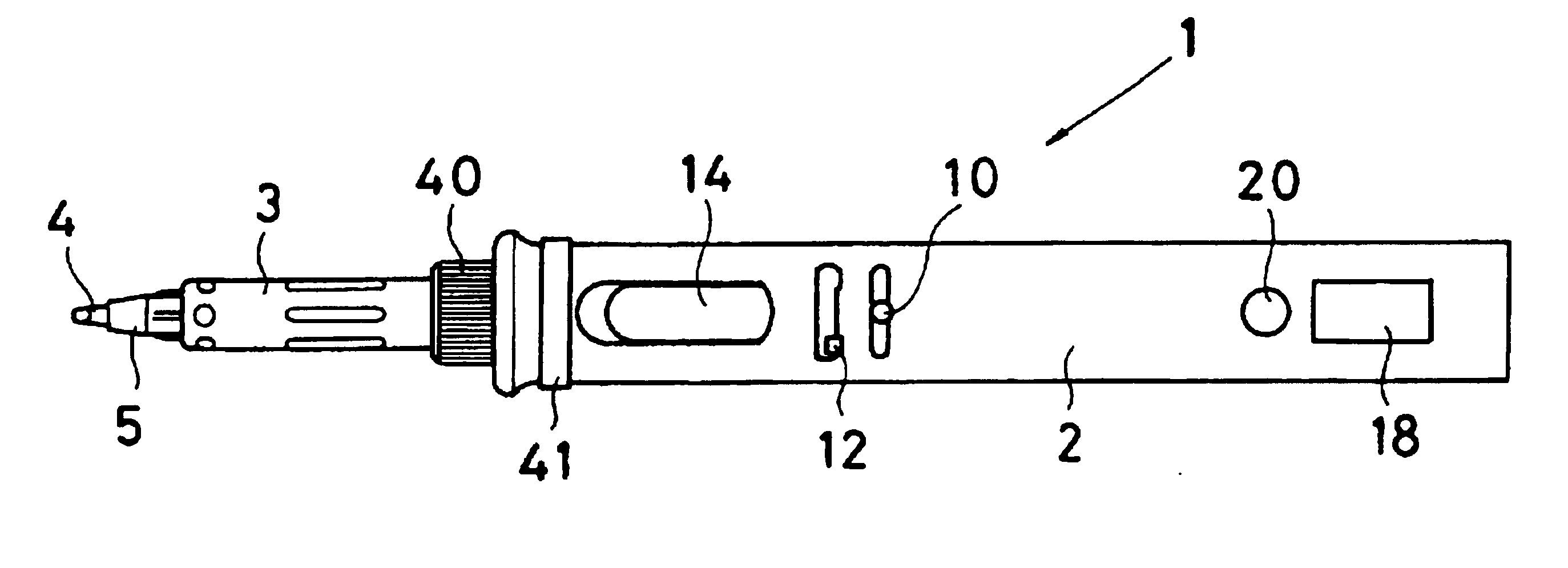
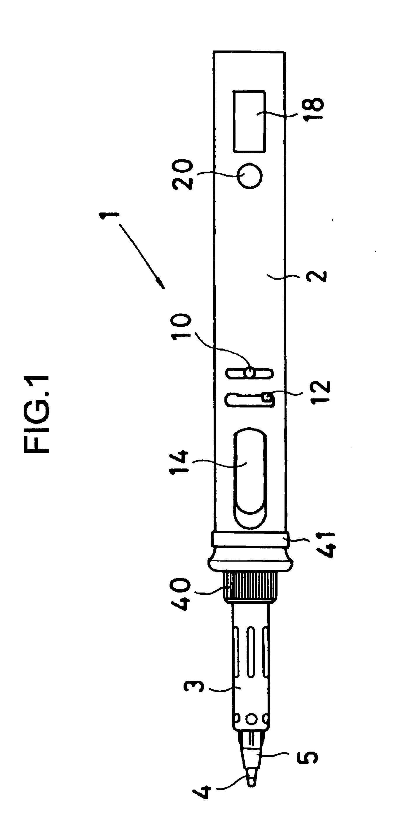
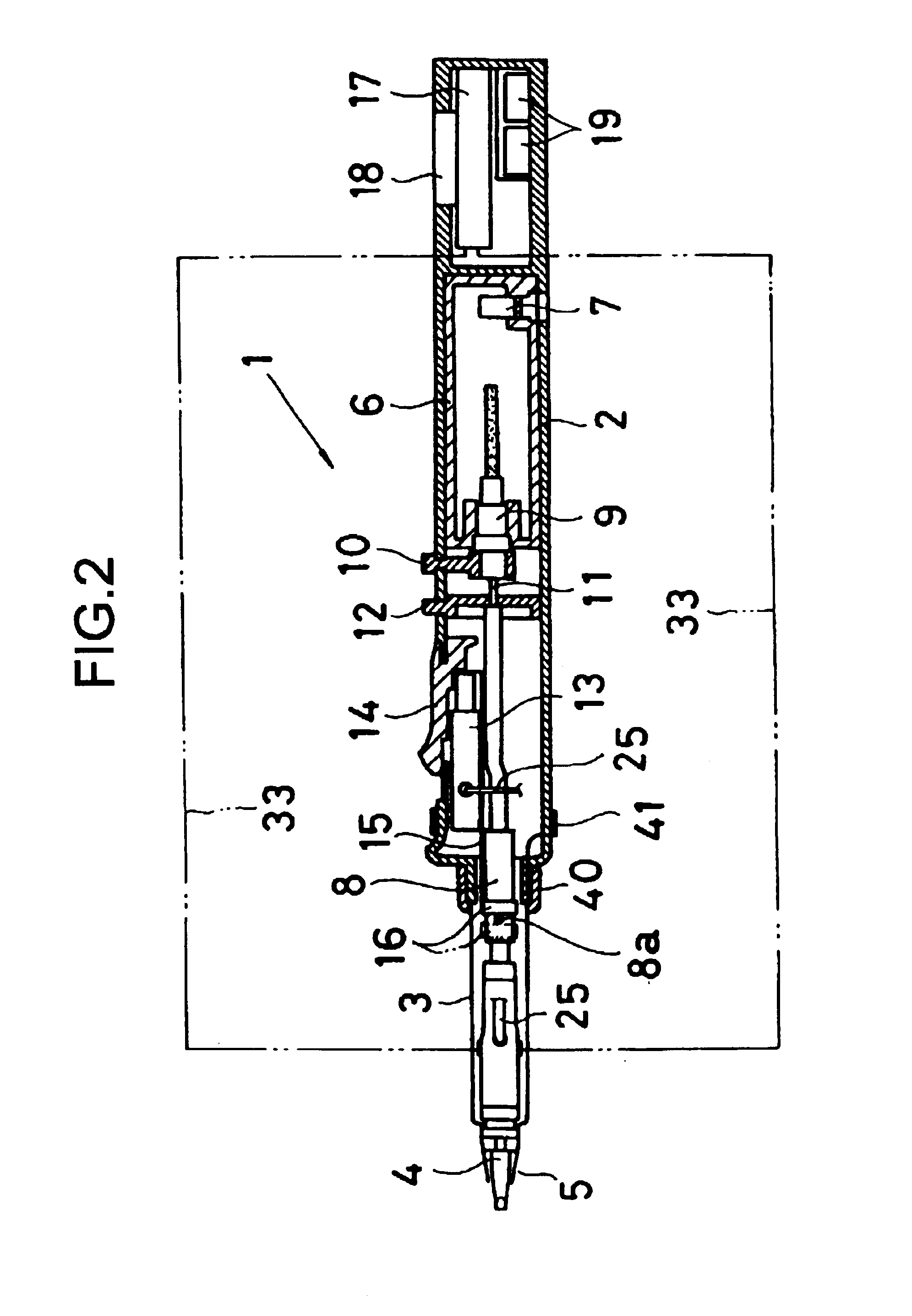
In this feature of the invention static charges accumulated on materials to be soldered, as well as static charges accumulated on the operator can be eliminated due to the charge elimination effect obtained from the combustion catalyst and the combustion exhaust gas, by connecting the operator and the soldering iron tip electrically by way of the electroconduction mechanism. Further, since the periphery for the area to be soldered is heated preliminarily by the heat of the combustion exhaust gas, even when the size of the soldering iron tip is decreased, insufficiency of the heat capacity of the tip can be compensated by the combustion exhaust gas. Further, since the periphery of the soldering iron tip is surrounded with the inert combustion exhaust gas, the soldering iron tip can be prevented from oxidation to enhance the working life.
Then, an operator who conducts soldering operation can eliminate static charges quire unconsciously by merely holding the grip, during usual soldering operation for charge elimination, and this does not increase operator's burden at all.

Problems solved by technology

However, the soldering iron using the liquefied gas involves a problem caused by static electricity charged on an operator or materials to be soldered.
Such static charges may often damage electronic parts to be soldered.
In addition, the gas iron also has the following problem.
However, when the size of the soldering iron is decreased, the size of the soldering iron tip has also to be decreased inevitably to result in insufficiency of heat capacity, which worsens the efficiency of the soldering operation.
Particularly, in a case of using Pb-free solder, since a larger heat capacity is required for the soldering chip, this causes a more significant problem.
Further, since the soldering iron tip is exposed to a high temperature, the surface is violently oxidized to greatly shorten the working life of the tip.

Method used


Image

  • Soldering tool
  • Soldering tool
  • Soldering tool

Examples


example

The present inventors have made an experiment for the temperature difference between the iron tip member 26 and the base end of the heat collector 30 by using the soldering iron tip 4 shown in FIG. 3 and obtained a result shown in FIG. 12.

That is, the present inventors have manufactured three types of soldering iron tips 4. The length for the heat collector 30 was 20 mm for each of them and the diameter thereof was 2.0 mm, 2.5 mm and 3.0 mm, respectively. Then, each of the iron tip member 26 of each soldering iron tip 4 was immersed in an oil bath at 100° C. and heated rapidly, and change with lapse of time of temperature for the heat collector 30 was measured. In FIG. 12, a graph A shows a characteristic curve in a case of 2.0 mm diameter, a graph B shows a characteristic curve in a case of 1.5 mm diameter, and a graph C shows a characteristic curve in a case of 3.0 mm diameter.

As apparent from FIG. 12, it can be seen that even when the length of the heat collector 30 was 20 mm, th...


PUM

PropertyMeasurementUnit
diameteraaaaaaaaaa
diameteraaaaaaaaaa
diameteraaaaaaaaaa

Abstract

A soldering iron capable of eliminating static charges accumulated on an operator or materials to be soldered simply without using no particular charge elimination device, the soldering iron comprising a combustion catalyst for complete combustion of a gas mixture of a fuel gas and air, a soldering iron tip heated by the combustion catalyst, a gas conduit for exhausting a combustion exhaust gas from the combustion catalyst along the outer circumference of the soldering iron tip toward the top end, and an electric conduction mechanism for electrically connecting an operator for conducting soldering and the soldering iron tip, fuel gas combustion products which are ionized and forming steams upon catalytic combustion contributing to charge elimination.

Description

BACKGROUND OF THE INVENTION1. Field of the InventionThe present invention concerns a soldering iron using a liquefied gas such as a butane gas or propane gas as a fuel gas and, more in particular, it relates to a soldering iron capable of eliminating electrostatic charges accumulated on an operator or materials to be applied with soldering.2. Statement of the Related ArtSoldering tools or soldering irons using liquefied gas such as a butane gas and a propane gas as the fuel gas have generally been known. The soldering gas irons have advantages in that they are simple and convenient and easy to use since they require no external power supply and have no electric cords, as well as have no worry of troubles caused by electric leak current since electric heaters are not used as a heat source like electric irons and thus they are suitable to soldering operation for electronic circuits and the likes.However, the soldering iron using the liquefied gas involves a problem caused by static el...

Claims


Application Information

Patent Timeline
Patent Type & Authority Patents(United States)
IPC IPC(8): B23K3/02B23K1/00F23D14/40F23C13/00
CPCB23K3/022
Inventor HIRANO, TSUMORUNAKAMURA, MASARU
Owner NAKAJIMA DOKOSHO CO LTD
Why Eureka
Try Eureka