Heat exchanger for high stage generator of absorption chiller

Inactive Publication Date: 2005-04-12
CARRIER CORP
View PDF3 Cites 7 Cited by
  • Summary
  • Abstract
  • Description
  • Claims
  • Application Information

AI Technical Summary

Benefits of technology

According to the present invention, in a standard liquid tube type high stage generator, a partition plate is positioned toward the end of the heat exchanger dividing the high and low pressures of a high and low stage of a triple or double effect absorption chiller cycle. The section from the fire tube up to the partition plate brings down the flue temperature up to approximately 650 F for a triple effect and up to 400 F for a double effect cycle. There is significant amount of energy remaining in the exhaust, which is recovered by preheating or boiling solution at a lower pressure in the remaining section of the flue passage, called flue gas recuperator (FGR). The FGR is a flooded type heat exchanger. Although the liquid tubes of both high stage generator and FGR section are shown to be of the same

Problems solved by technology

As this process continues, the lithium bromide becomes diluted, reducing its absorption capaci

Method used


Image

  • Heat exchanger for high stage generator of absorption chiller
  • Heat exchanger for high stage generator of absorption chiller
  • Heat exchanger for high stage generator of absorption chiller

Examples


embodiment 2

am of Solution Leaving Absorber

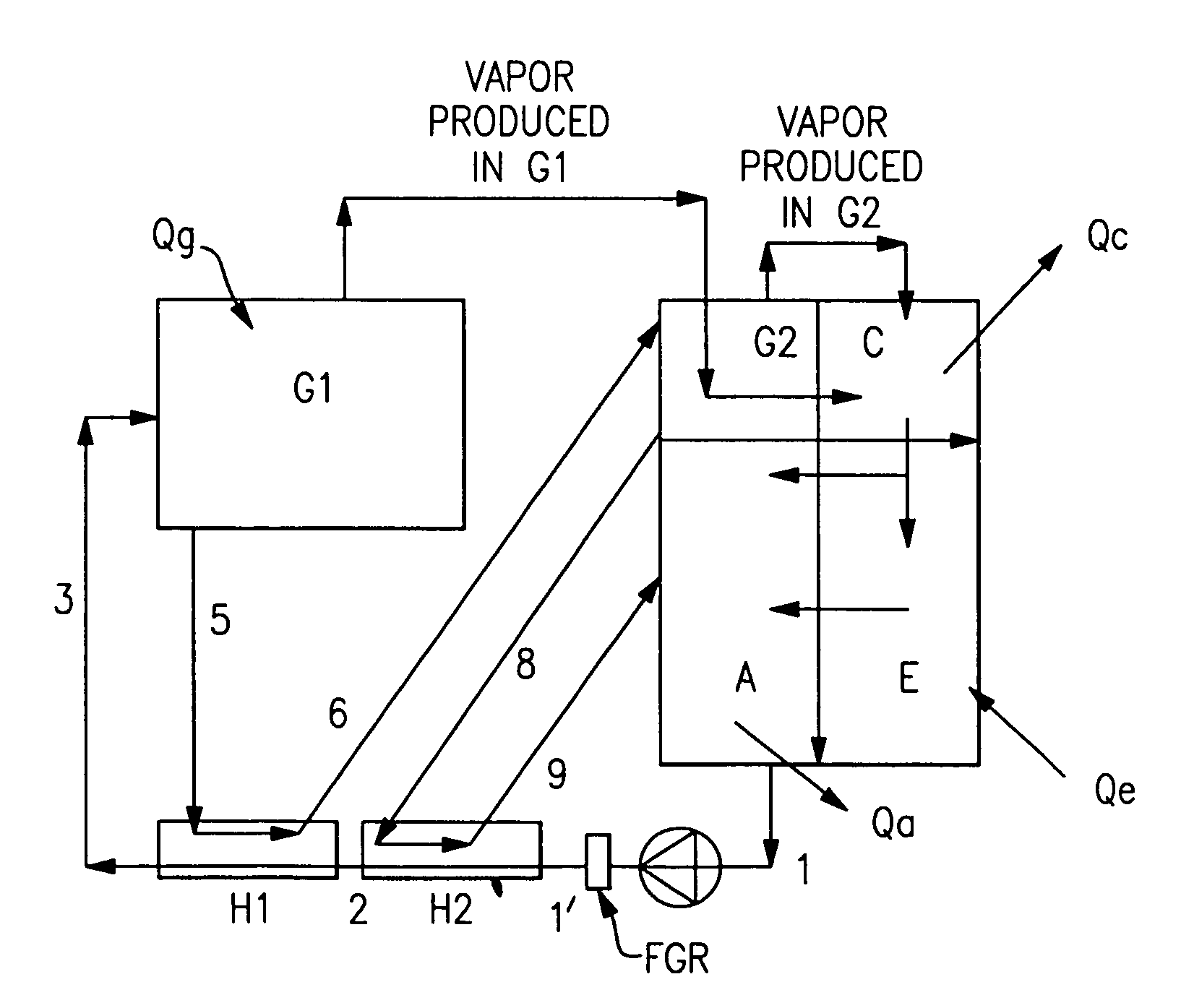
As shown in FIG. 7(b), a fraction of total solution flow leaving the absorber is passed through the FGR. If 10% of total energy input is recovered in FGR, and 10% of solution flow rate leaving absorber is bypassed in the FGR, then temperatures as shown in FIG. 7(b) can be achieved. Note that 1′–3′ is the heating of solution with FGR. In this situation, the risk of crystallization is the same as the baseline case of FIG. 1.

embodiment 3

am of Weak Solution Leaving H2

This embodiment is illustrated in FIGS. 8(a) and (b). It is similar to Embodiment 2, except instead of splitting a stream of solution leaving the absorber, a stream of weak solution is split leaving H2. In this case, the H2 leaving solution temperature is still at 72° C., but the split stream is heated with the FGR to 145° C., and the rest of the solution is heated to 145C in H1. In this embodiment, 2–3 is heating carried out in H1 while 2′–3′ is heating in the FGR.

embodiments 2 and 3

In embodiments 2 and 3, weak solution entering low temperature heat exchanger (H2) or high temperature heat exchanger (H1) is heated in FGR. Heated weak solution leaving FGR is mixed with either weak solution leaving H2 or weak solution leaving H1. It is important to bring the temperature of heated solution leaving FGR in close proximity to the temperature of solution in which it is being mixed to avoid mixing losses and improve thermodynamic efficiency of absorption cycle. This can be accomplished by two methods. First method is mechanical device such as a fixed orifice or a field adjustable valve. Second method is an electronically controlled valve.

FIG. 6(c) shows a scheme for embodiment 2, where heated solution from FGR is mixed with heated weak solution leaving H1. At full load, flue gas leaving high stage generator at full load is typically at 190–210C depending on efficiency of high stage generator. Weak solution leaving absorber is at typically at 38C. Assuming flue gas tempe...


PUM


Abstract

An absorption cooling machine of the type which uses a refrigerant and an absorbent and which includes a high stage generator, absorber, condenser, heat exchangers, and an evaporator and means for connecting the components to one another to form a closed absorption cooling system. The solution side of the high stage generator is fluidically divided into two sections with a partition plate whereby gas exiting one section at relatively high temperature is further cooled in a second section called a flue gas recuperator (FGR) to improve overall burner efficiency.

Description

BACKGROUND OF THE INVENTIONThe invention relates in general to an absorption cooling system and more specifically to an improved heat exchanger for a high stage generator of an absorption chiller.A direct-fired, double effect, absorption chiller / heater consists of an evaporator, absorber, condenser, high and low stage generators, separator, solution heat exchanges, refrigerant / solution pumps, burner and gas train assembly, purge, controls and auxiliaries. Water is used as the refrigerant in vessels maintained under low absolute pressure (vacuum). In the cooling mode, the chiller operates on the principle that under vacuum, water boils at a low temperature, thereby cooling the chilled water circulating through the evaporator tubes. A refrigerant pump is used to circulate the refrigerant water over the evaporator tubes to improve heat transfer.To make the cooling process continuous, the refrigerant vapor must be removed as it is produced. To accomplish this, a lithium bromide solution...

Claims


Application Information

Patent Timeline
IPC IPC(8): F25B15/00F25B27/02F25B33/00F25B15/02F25B15/06
CPCF25B15/008F25B33/00F25B27/02F25B15/06Y02B30/625F25B2333/003Y02P80/15Y02A30/274
Inventor GUPTE, NEELKANTH S.
Owner CARRIER CORP
Why Eureka
Try Eureka